

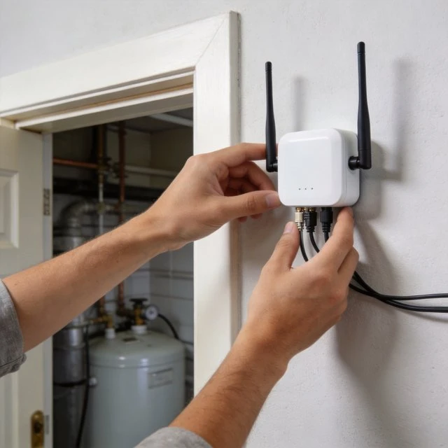
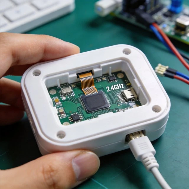
Smart home terminals-sensors, locks, lights, thermostats, and appliance accessories-most often rely on 2.4 GHz radios because the ecosystem (phones, hubs, access points) and silicon maturity make 2.4 GHz connectivity broadly interoperable. From an antenna perspective, the 2.4 GHz band is “small enough” that antennas can be realized inside compact plastic enclosures, yet “large enough” that ground-plane and housing choices still meaningfully shape range and packet reliability. A comprehensive antenna design and RF layout application note stresses that antenna design, enclosure, and layout can cause wide variation in RF range even with the same radio silicon and transmit power, and it provides concrete matching and tuning guidance for 2.4 GHz BLE-class products. Common terminal antenna implementations at 2.4 GHz include PCB trace antennas (e.g., meandered inverted-F), ceramic chip antennas, and peel-and-stick flexible PCB antennas. Practical layout guidance emphasizes: controlling feed-line impedance; maintaining keep-outs near the radiator; and reserving a matching network footprint, often a pi network, so the final resonance can be shifted in production without re-spinning the radiator geometry.
The application note explicitly recommends matching networks as a preferred practice versus relying only on physical length-trimming for tuning and provides example chip-antenna keep-out guidance (millimeter-scale clearance affecting return loss). Regulatory compliance also drives antenna choices. In Europe, harmonized standards for 2.4 GHz wideband data transmission equipment define spectrum-related requirements and test methods; the ETSI EN 300 328 series is widely used for demonstrating compliance for equipment operating in 2400-2483.5 MHz under relevant regulatory frameworks. For unlicensed spread-spectrum/digital modulation in the U.S. ISM bands, FCC rules such as 47 CFR Section 15.247 define technical constraints (e.g., conditions for frequency hopping and digitally modulated systems) that indirectly affect antenna design margins because they constrain allowed conducted/radiated power, bandwidth, and emissions behavior. On the protocol side, Bluetooth specifications (maintained by the Bluetooth SIG) define interoperable device behaviors, while IEEE 802.15.4 provides the PHY/MAC basis for Zigbee/Thread-class networks; these protocol constraints translate into sensitivity, modulation, and coexistence expectations that the antenna must support in the final product environment
Target Audience
- IoT hardware designers
- RF/layout engineers
- smart-home product teams
- compliance labs
Key Technical Points
- 2.4 GHz antenna choice is primarily about integration: ground-plane effects, plastic vs metal enclosures, matching network reserve, and repeatable tuning
- compliance constraints differ by region (ETSI EN 300 328 vs FCC Part 15 rules)
Practical Use Cases
- Thread/Zigbee sensors
- BLE beacons and wearables
- Wi-Fi smart plugs and appliances
- battery nodes where efficiency directly impacts range and battery life
Relevant Standards and Protocols
- Bluetooth Core Specification
- IEEE 802.15.4
- ETSI EN 300 328
- FCC 47 CFR Section 15.247
Typical Hardware Examples
- Taoglas FXP73 “Blue Diamond” 2.4 GHz flexible PCB antenna datasheet includes 2400-2500 MHz, dimensions 47 x 7 x 0.1 mm, and connector/cable details
- Johanson Technology 2450AT42B100E is cited in the antenna/layout guideline note as an example chip antenna requiring specific layout/clearance considerations
- Murata DNT24CA/PA module datasheet highlights integration ease via a built-in chip antenna (module-level example)
Deployment Considerations
- Keep-outs and ground clearance
- final-product tuning with matching components
- 2.4 GHz coexistence (Wi-Fi/BLE/802.15.4) in crowded spectrum
- region-specific test and documentation (ETSI/FCC)
GNSS integration
Need help choosing a GNSS or patch antenna?
Tell us your device size, ground plane, constellation, cable and mounting requirements. We can help match active, passive or embedded GNSS antenna options.
FAQ
Why do smart home IoT devices mostly use the 2.4 GHz band?
Because the surrounding ecosystem (phones, hubs, access points) and silicon maturity make 2.4 GHz broadly interoperable. The band is also small enough that antennas fit inside compact plastic enclosures, yet large enough that ground-plane and housing choices still meaningfully shape range and packet reliability.
What antenna types are common for 2.4 GHz terminals?
Common implementations include PCB trace antennas such as the meandered inverted-F, ceramic chip antennas, and peel-and-stick flexible PCB antennas.
How should a 2.4 GHz antenna be tuned in production?
Reserve a matching-network footprint, often a pi network, so the final resonance can be shifted in production without re-spinning the radiator geometry. Matching networks are the preferred tuning approach, rather than relying only on physical length-trimming.
Which compliance standards affect 2.4 GHz antenna design?
In Europe, the ETSI EN 300 328 series covers 2400-2483.5 MHz wideband data equipment. In the United States, FCC 47 CFR Section 15.247 defines technical constraints for unlicensed spread-spectrum and digitally modulated systems in the ISM band.
Ready to specify a product?
Get product suggestions and quotation details for your application.
Tell us your device size, ground plane, constellation, cable and mounting requirements. We can help match active, passive or embedded GNSS antenna options.

