

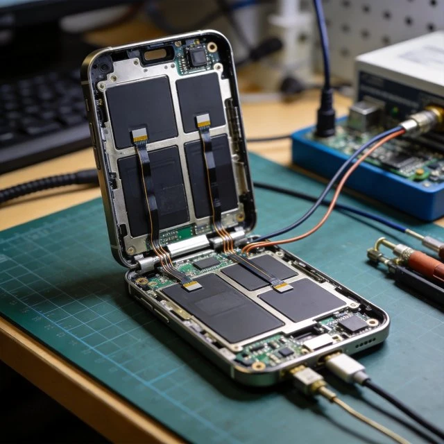
Modern smartphones and wearables are “antenna-dense” terminals: they may simultaneously support sub-6 GHz cellular, mmWave cellular, Wi-Fi, Bluetooth, GNSS, and sometimes other radios. The antenna system is therefore not a single part but a co-designed RF-and-mechanical subsystem where placement, grounding, and coexistence are as important as the radiator geometry. mmWave smartphones, for example, commonly depend on phased-array style antenna modules plus beam management (beamforming/steering/tracking) to overcome propagation loss and blockage; a published example describes a mmWave antenna module family supporting 5G NR mmWave bands n257/n260/n261 and explicitly calls out beamforming, beam steering, and beam tracking as enabling features. At sub-6 GHz, compact handset antennas often use structures derived from monopoles, including Planar Inverted-F Antennas (PIFAs). A vendor technical note characterizes PIFAs as a monopole-derived structure with a shorting arm that helps impedance matching (often reducing external matching loss), and highlights robustness in changing environments relative to some other small-form antennas. In practice, multi-antenna layouts needed for MIMO and multi-band operation increase mutual coupling risks and raise the value of isolation strategies and careful ground segmentation, especially as enclosure materials and user proximity detune resonance and reshape patterns.
Two test ecosystems strongly shape consumer-device antenna engineering. First, cellular conformance testing increasingly emphasizes OTA metrics such as TRP and TRS as standardized ways to assess radiated power and sensitivity at the device level. An ETSI specification explicitly scopes FR1 TRP/TRS conformance testing methodologies for NR SA and EN-DC, demonstrating that “antenna performance” is operationalized as something verified over-the-air, not only by conducted RF ports. Second, industry certification programs position OTA test plans as an “industry standard” approach for simulated real-world performance measurement of a device’s antenna system. Finally, consumer terminals must account for human exposure constraints; FCC guidance documents frame evaluation methods and limits for RF exposure compliance, and global guideline bodies publish RF exposure guidance spanning 100 kHz-300 GHz. These constraints feed back into antenna placement, power management, and “body-worn” separation assumptions
Target Audience
- Smartphone/wearable RF system architects
- antenna engineers
- product compliance engineers
- ODM/OEM mechanical integration teams
Key Technical Points
- Multi-radio coexistence and mechanical detuning dominate
- mmWave requires beam management with phased arrays
- OTA TRP/TRS frameworks formalize antenna validation
- exposure limits constrain placement and power
Practical Use Cases
- Premium 5G smartphones (sub-6 + mmWave)
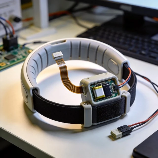
- smartwatches/fitness bands with BLE + Wi-Fi + GNSS
- consumer AR/VR wearables with tight form factors
Relevant Standards and Protocols
- NR UE RF requirements and OTA conformance testing (ETSI/3GPP)
- CTIA OTA device performance test plans
- RF exposure evaluation guidance and limits from FCC and ICNIRP
Typical Hardware Examples
- Qualcomm QTM052 mmWave antenna module family (bands n257/n260/n261 mentioned in the cited document)
- PIFA form-factor design tradeoffs summarized by Abracon technical note
Deployment Considerations
- Factory calibration and OTA verification
- hand/head/body detuning
- coexistence mitigation among radios
- exposure/SAR evaluation and documentation alignment with intended use positions
GNSS integration
Need help choosing a GNSS or patch antenna?
Tell us your device size, ground plane, constellation, cable and mounting requirements. We can help match active, passive or embedded GNSS antenna options.
FAQ
Why are smartphones and wearables called antenna-dense terminals?
They may simultaneously support sub-6 GHz cellular, mmWave cellular, Wi-Fi, Bluetooth, GNSS, and other radios, so the antenna system is a co-designed RF-and-mechanical subsystem where placement, grounding, and coexistence matter as much as the radiator geometry.
How do mmWave smartphones overcome propagation loss?
They commonly depend on phased-array style antenna modules plus beam management, including beamforming, beam steering, and beam tracking, across 5G NR mmWave bands such as n257, n260, and n261.
What antenna structure is common for sub-6 GHz handsets?
Compact handset antennas often use Planar Inverted-F Antennas (PIFAs), a monopole-derived structure with a shorting arm that helps impedance matching and improves robustness in changing environments.
How is smartphone antenna performance validated?
Through over-the-air metrics such as TRP and TRS under conformance methodologies like the ETSI FR1 framework and CTIA OTA test plans, while FCC and ICNIRP RF-exposure limits constrain antenna placement and power.
Ready to specify a product?
Get product suggestions and quotation details for your application.
Tell us your device size, ground plane, constellation, cable and mounting requirements. We can help match active, passive or embedded GNSS antenna options.

