

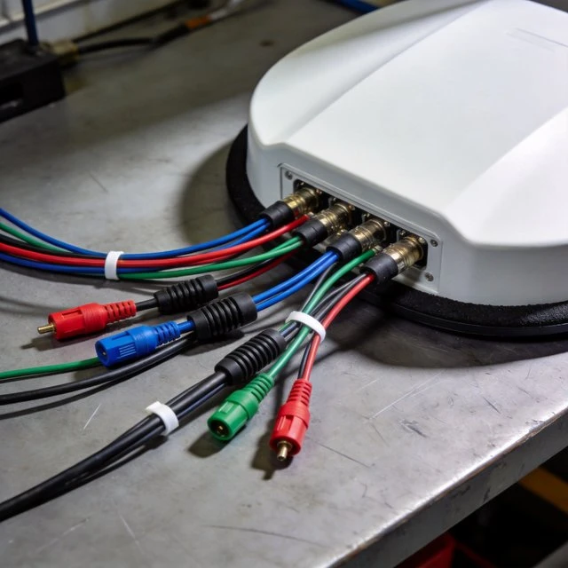
Automotive terminals face a different antenna reality than handhelds: the vehicle body can provide a large conductive reference (useful for some radiators), but the RF environment is harsh-wide temperature ranges, vibration, water ingress, long cable runs, and strict electromagnetic compatibility (EMC) limits. The “terminal antenna” in automotive is often a multi-function roof antenna module (commonly “shark fin” style) that consolidates multiple services-cellular, GNSS, Wi-Fi, and broadcast radio-into one sealed mechanical unit, simplifying OEM assembly and improving repeatability across vehicle platforms. A representative shark fin antenna datasheet describes a 4-in-1 permanent-mount roof solution supporting LTE/3G/2G frequency ranges, GNSS L1 constellations, dual-band Wi-Fi (2.4/5.8), and AM/FM, and specifies an IP67 waterproof enclosure with coax pigtails and SMA connectors (with fakra optional). A second shark fin example from another vendor similarly combines 4G, Wi-Fi, and active GNSS functions in a direct-mount form factor, illustrating that multi-radio consolidation is a standard market pattern. Automotive antenna deployment is inseparable from EMC standards.

CISPR 25 (published via the IEC webstore) defines test methods for controlling radio frequency emissions from vehicles and components, and is used by OEMs and suppliers to ensure on-board receivers are protected from conducted and radiated disturbances. Immunity standards such as ISO 11452 describe methodologies for evaluating component immunity to narrowband radiated electromagnetic energy from off-vehicle sources, reflecting the reality that vehicle terminals must both avoid emitting interference and maintain performance under external RF fields. In connected vehicles, the antenna module is also a system integrator for coexistence: multiple coax lines and filters must preserve GNSS sensitivity while cellular radios transmit at high power; Wi-Fi hotspots and sometimes V2X radios add more coupling paths. Even when a single housing is used, the internal partitioning, cable routing, and connectorization must be designed to minimize intermodulation and blocker effects. The GNSS integration guidance cited earlier generalizes here: nearby transmitters and digital noise sources can substantially degrade GNSS if not filtered and spatially controlled
Target Audience
- Automotive antenna/module designers
- telematics OEMs
- Tier-1 integrators
- vehicle EMC engineers
Key Technical Points
- Multi-service consolidation
- sealed mechanical + connectorized RF
- OEM-grade environmental constraints
- CISPR 25 emissions expectations
- ISO 11452 immunity expectations
- GNSS coexistence with cellular/Wi-Fi transmitters
Practical Use Cases
- Telematics control units
- fleet and heavy equipment tracking
- in-vehicle Wi-Fi hotspots
- GNSS navigation and stolen-vehicle recovery
- connected infotainment
Relevant Standards and Protocols
- CISPR 25
- ISO 11452
- GNSS L1 constellations/bands as integrated
- (when present) cellular NR/LTE and Wi-Fi regulatory standards
Typical Hardware Examples
- Taoglas MA1060 “Raptor I” 4-in-1 shark fin antenna with LTE, GNSS, Wi-Fi, and AM/FM support plus IP67 sealing and SMA/Fakra options
- Pulse Electronics GNSSDM700/5800SSS shark fin series with 4G, Wi-Fi, and active GNSS direct-mount architecture
Deployment Considerations
- Roof mounting for clear sky view and improved radiation
- cable-loss management over vehicle harness lengths
- sealing/IP requirements
- OEM EMC pre-compliance against CISPR 25
- immunity testing alignment (ISO 11452)
- careful GNSS filtering and separation from high-power cellular paths
Interference environment
Need an antenna matched to a high-interference project?
Tell us the frequency range, installation space and interference scenario. We can suggest suitable anti-jamming or specialty antenna options.
FAQ
What is a roof-mounted multi-function automotive antenna?
It is often a shark fin style module that consolidates multiple services, such as cellular, GNSS, Wi-Fi, and broadcast radio, into one sealed mechanical unit, simplifying OEM assembly and improving repeatability across vehicle platforms.
What does a typical automotive shark-fin antenna support?
A representative 4-in-1 permanent-mount example supports LTE/3G/2G frequency ranges, GNSS L1 constellations, dual-band Wi-Fi (2.4/5.8 GHz), and AM/FM, in an IP67 waterproof enclosure with coax pigtails and SMA connectors, with Fakra optional.
Which EMC standards apply to automotive antennas?
CISPR 25 defines test methods for controlling radio frequency emissions from vehicles and components, while immunity standards such as ISO 11452 evaluate component immunity to narrowband radiated electromagnetic energy from off-vehicle sources.
How is GNSS protected inside a multi-radio roof module?
Internal partitioning, cable routing, and connectorization must be designed to minimize intermodulation and blocker effects, and nearby cellular and Wi-Fi transmitters and digital noise must be filtered and spatially controlled to preserve GNSS sensitivity.
Ready to specify a product?
Get product suggestions and quotation details for your application.
Tell us the frequency range, installation space and interference scenario. We can suggest suitable anti-jamming or specialty antenna options.

