
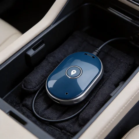
A GPS tracker antenna decides whether your device locks on in half a minute or drops in and out of coverage all day. The positioning module matters far less than most buyers expect — the antenna, where it sits, and the cable between them set the real limit.
Short answer
- Single-band GPS L1 patch (1575.42 MHz) — enough for a compact tracker when you control the enclosure and give the patch the ground plane its datasheet asks for.
- Active GPS/GLONASS antenna — use it as soon as the antenna sits away from the board, behind metal, or at the end of a cable run.
- Magnetic-mount external antenna — use it when the tracker itself lives inside a metal box, cabinet or vehicle body.
- Multi-constellation (GPS + GLONASS + Galileo + BeiDou) — worth the cost in cities, ports and logistics yards where half the sky is blocked.
The rest of this guide follows the same order an engineer actually decides in: bands and constellations, active vs. passive, gain and cable budget, mounting and ground plane, then the tests to run before the design goes to production.
What a GPS Tracker Antenna Does
The antenna catches the satellite signal and hands it to the positioning chip. The hard part is how weak that signal is. GPS interface specification IS-GPS-200 does not even expect a strong day at the receiver: it states that the maximum received L1 C/A power should not exceed −153.0 dBW, which is under one femtowatt (IS-GPS-200N, §6.3.1). For GLONASS, ITU-R Recommendation M.1477 lists a minimum received power at the antenna input of −161 dBW (ITU-R M.1477).
That is the whole reason antenna choice matters. At those levels, a couple of dB lost in a bad mounting position, a cheap cable or a noisy switching regulator inside your own product is not a rounding error — it is the difference between a 30-second fix and no fix at all.
Most trackers today also listen to more than GPS. Adding GLONASS, Galileo or BeiDou increases the number of satellites in view, which is what keeps positions stable between buildings, containers and trees. If your device only ever works in open sky, single-band GPS is still a legitimate, cheaper choice.
Key Selection Factors for Tracker Antennas
Frequency and GNSS constellation support
Start from the module datasheet, not from the antenna catalogue. The band plan decides everything else:
| Constellation | Open signal | Centre frequency |
|---|---|---|
| GPS | L1 C/A, L1C | 1575.42 MHz |
| Galileo | E1 | 1575.42 MHz |
| BeiDou | B1C | 1575.42 MHz |
| GLONASS | L1OF | 1602 MHz (channels at 1602 + n × 0.5625 MHz) |
Sources: GPS.gov, ESA Navipedia – Galileo Signal Plan, GLONASS Information and Analysis Center.

There is a useful detail buried in that table. GPS, Galileo and BeiDou B1C all share exactly the same carrier, so a plain 1575.42 MHz antenna already gives you three constellations. GLONASS is the odd one out: its FDMA channels sit about 27 MHz higher, so covering it means the antenna’s passband has to stretch to roughly 1575–1610 MHz. That is why “GPS/GLONASS” antennas exist as a separate product line, and why buying one changes nothing if your module never enables GLONASS. Check the module’s enabled constellations first — many low-cost trackers ship with GPS-only firmware.
For single-band designs, a compact GPS ceramic patch antenna is enough. For fleet management, smart logistics or rugged outdoor terminals, a wider GPS/GLONASS antenna is the safer choice.
Active vs. passive antenna design
A passive antenna is just the radiating element. An active antenna adds an LNA (low-noise amplifier — a small amplifier placed right at the antenna) plus a filter, and it needs DC power, usually 3–5 V fed up the same coax from the module’s bias pin.
The rule is simpler than most datasheets make it sound:
- Antenna within a few centimetres of the module → passive is fine and saves current.
- Antenna at the end of a cable, outside the enclosure, or behind metal → go active.
Why the placement matters more than the amplifier: in a receiver chain, the first stage sets the noise floor. An LNA at the antenna amplifies the signal before the cable attenuates it, so the cable loss barely hurts. The same LNA sitting after the cable, inside the box, amplifies signal and cable noise together and recovers almost nothing. “Active” is not a performance upgrade you bolt on at the end — it is a decision about where the first gain stage lives.

Two integration items get missed regularly:
- Confirm the module’s bias voltage and its maximum bias current, then check the antenna’s LNA current draw fits inside it. On battery-powered assets this current also runs whenever the receiver is on, so it belongs in the power budget.
- If your board feeds bias through an inductor or ferrite, make sure that path is rated for the antenna’s current, and that a shorted cable will not damage the module.
Gain, cable length and connector type
The “28 dB” or “38 dB” on an active antenna label is LNA gain, not antenna gain, and it is the number buyers most often misread. LNA gain does not improve sensitivity — it only carries the signal across whatever loss comes after it. Pick it to cover your losses, not to be the biggest number available.
A workable budget, using your own cable datasheet rather than a made-up figure:
LNA gain needed ≈ cable loss (dB/m at 1.6 GHz × length) + connector loss + splitter/filter loss + a few dB marginLook up dB/m at 1.6 GHz for the exact coax you plan to buy — thin cables such as 1.13 mm micro-coax and RG-174 lose several times more per metre than RG-58 or LMR-type cable, and a 5 m run of the wrong coax can eat more than the module’s whole margin. Treat this as an engineering estimate for shortlisting, then confirm on real hardware.
Too much gain is also a real failure mode: an over-amplified front end can be driven into compression by a nearby LTE or Wi-Fi transmitter, so satellite count drops exactly when the tracker starts reporting. Match gain to loss, then stop.
Before locking the BOM, pin down cable type, length, connector format (SMA, MMCX, IPEX/u.FL, Fakra), gender and polarity, and the bias voltage for active parts. Connector mismatches are the single most common cause of a re-order.
Mounting environment
Asset trackers sit inside plastic housings, under dashboards, on containers, in outdoor cabinets or on vehicle bodies. Embedded ceramic antennas work when you control the PCB and the enclosure. Magnetic-mount antennas are the answer when the antenna has to get outside a metal box or onto a vehicle roof.
The ground plane is not optional. A ceramic patch is tuned against the metal underneath it, so the ground plane is part of the antenna. Shrink it below the size the datasheet assumes and the resonance shifts off 1575.42 MHz — the antenna is not “weaker”, it is mistuned, and no amount of LNA gain fixes that. Practical consequences:
- Use the ground plane dimensions in the patch datasheet as a hard layout requirement, not a suggestion.
- Keep the patch centred on that ground area, with the pin position as specified.
- If the enclosure forces a small board, choose a chip or helical antenna designed for a small ground plane instead of squeezing a patch.
Also check the boring items early: IP rating for outdoor and wash-down use, UV resistance for anything exposed for years, vibration and cable strain relief on vehicles, and the operating temperature range for containers and engine bays.
Recommended Rftech Product Paths
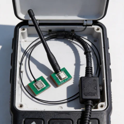
If you need a ready-to-integrate tracker device, start with the GL-DYCA003 GPS Tracker, GL-DYCA-WD01 GPS Tracker and GL-DYCA-P2 GPS Tracker. These options are useful for evaluating complete tracker form factors before customizing antenna placement, power design or enclosure details.
For module-level positioning designs, compare GPS/GLONASS antenna products such as the GL049-12 GPS GLONASS Antenna and GLSY103 GPS GLONASS Antenna. These are more relevant when the tracker electronics are already selected and the engineering task is antenna integration.
For vehicle, gateway and cabinet installations, external magnetic-mount antennas can simplify field deployment. The GL-DY284 Magnetic Mount Antenna and GL-DY016 Magnetic Mount Antenna are examples of products to review when the tracker or IoT terminal requires external mounting flexibility.
GNSS integration
Need help choosing a GNSS or patch antenna?
Tell us your device size, ground plane, constellation, cable and mounting requirements. We can help match active, passive or embedded GNSS antenna options.
Integration Checklist Before Production
Bench results from a bare board tell you almost nothing about the finished product. Always retest in the final enclosure, in the real mounting position, with the battery, brackets, display and cable harness in place.
A short pre-production list:
- [ ] Cold start and hot start time to first fix, in the assembled product
- [ ] Satellite count and C/N₀ (carrier-to-noise density, the receiver’s own signal-quality readout) with the enclosure closed
- [ ] Position stability while stationary, and while driving a repeatable route
- [ ] The same tests with the cellular modem transmitting at full power
- [ ] Temperature extremes and a vibration run for vehicle or container use
That fourth item is the one that catches teams out. Log C/N₀ with the modem idle, then during an upload. If the average drops by several dB when LTE-M, NB-IoT, 4G or 5G transmits, you have a coexistence problem — usually antenna spacing, cable routing or a missing filter — not a bad GNSS antenna. For multi-antenna planning, our article on 5G IoT antenna solutions goes further.
How Rftech Helps with Tracker Antenna Projects
Rftech supplies GPS tracker products, GNSS antennas, magnetic-mount antennas and custom RF antenna assemblies for IoT and industrial applications. We can help evaluate frequency requirements, cable and connector options, enclosure constraints, mounting methods and product-level antenna matching before mass production.
If you are selecting antennas for fleet tracking, asset monitoring, smart logistics or industrial IoT hardware, share your module, installation environment and target market. Our team can recommend a tracker antenna path that fits both RF performance and manufacturing requirements.
FAQ
What does a GPS tracker antenna actually do?
It receives weak GNSS satellite signals and passes them to the positioning chipset. A good antenna choice helps shorten time to first fix, improve location stability, and reduce intermittent tracking gaps.
Which GNSS bands do tracker antennas need to support?
GPS L1, Galileo E1 and BeiDou B1C all sit at 1575.42 MHz, so one L1 antenna covers three constellations. GLONASS L1OF is centred at 1602 MHz, so supporting it requires a wider antenna passband. Match this to the constellations your module actually has enabled.
Do GPS tracker antennas need a ground plane?
Ceramic patch antennas do — the ground plane is part of the tuned structure, and using a smaller one than the datasheet specifies shifts the resonant frequency away from 1575.42 MHz. If your board is too small, use a chip or helical antenna designed for small ground planes instead.
Do GPS antennas need power?
Only active ones. They contain an LNA powered by a DC bias, typically 3–5 V, sent through the same coaxial cable from the receiver module. Check the module’s bias voltage and maximum bias current against the antenna’s current draw before you commit.
When should a tracker use an active rather than a passive antenna?
Active antennas include an LNA and are useful when the antenna is placed away from the main board or connected through a cable, such as external, vehicle-roof, or cabinet mounting, to compensate for cable and connector loss.
What should be validated before a tracker antenna goes to production?
Validate the antenna in the final enclosure and mounting position, testing cold start, hot start, location stability, satellite count, and performance while moving, and check coexistence with cellular, Wi-Fi, Bluetooth, or LoRa antennas.
Ready to specify a product?
Get product suggestions and quotation details for your application.
Tell us your device size, ground plane, constellation, cable and mounting requirements. We can help match active, passive or embedded GNSS antenna options.
Ask our AI antenna assistant. Enter a keyword or question for a free answer based on this article, Global RF Tech content, and general antenna/RF knowledge.
Do not submit confidential or personal information. Privacy Policy




