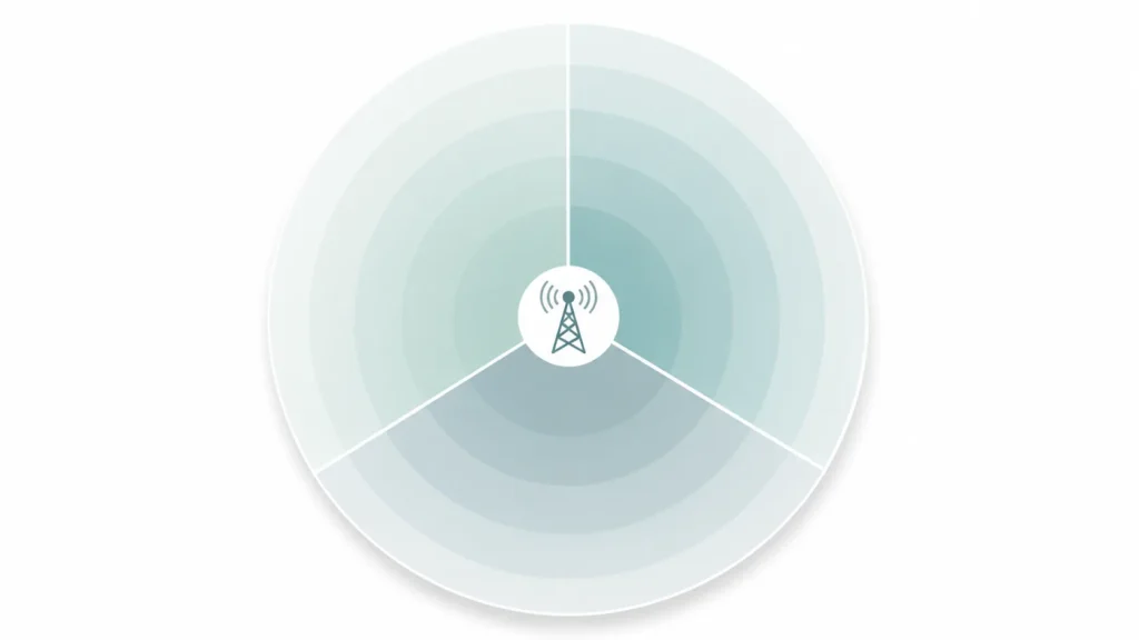
Sectorized antennas split one cell site into directional slices — usually three 120° panels, four 90° panels or six 65° panels — so the same spectrum serves several groups of users at once instead of one.
Short answer
- Start with 3 × 120°. ITU-R reference macro-cell parameters assume three sectors, 65° horizontal beamwidth and frequency reuse 1.
- Narrowing the azimuth beam is where the gain comes from: roughly 4.8 dB at 120°, 6.0 dB at 90° and 7.4 dB at 65°, compared with a 360° omni that has the same elevation beam.
- A datasheet beamwidth is a −3 dB number, not the sector edge. Plan seams with 10–15% overlap or you get handover drops.
- Downtilt, front-to-back ratio and polarization decide whether the array works. Gain alone does not.
The real decision is sector count, and it sets every other line on the datasheet: beamwidth, gain, port count, tilt range, even the bracket. So start there, and use the judgement criteria below rather than a gain number.
The three standard layouts
| Layout | Beamwidth per sector | Where it fits | The catch |
|---|---|---|---|
| 3 × 120° | 120° | Standard macro cell, WISP base station, rural coverage | Cheapest and simplest, lowest per-sector capacity |
| 4 × 90° | 90° | Urban sites, campus networks | More capacity, more radios to coordinate |
| 6 × 65° | 65° | Dense urban, stadiums, high-capacity 5G | Best capacity and gain, least forgiving to install |
| 1–2 sectors | 90°–180° | Roads, valleys, coastlines with users on one side | No full circle, and that is the point |
Two details hide behind the tidy math.
The first: a datasheet beamwidth is a −3 dB figure, meaning the angle at which radiated power has dropped to half of boresight. It is not the edge of usable coverage — signal keeps going well past it. Sector planning is usually done at the −6 dB or −10 dB points, which is why a “120°” panel is specified a few degrees wider than the nominal wedge, so neighbouring sectors overlap slightly instead of leaving a dead zone at the handover seam.
The second: “beamwidth × count ≥ 360°” only holds when every antenna in the array is the same model. Three roughly-120° panels from different vendors rarely tile cleanly, because each vendor draws its sector edge at a different point on the pattern.

How much gain does narrowing the beam actually buy?
You can size this before any quote arrives. ITU-R Recommendation F.1336 gives a provisional relationship for sectoral antennas: peak gain ≈ 31000 / (azimuth 3 dB beamwidth × elevation 3 dB beamwidth), both in degrees. Hold the elevation beam constant and compare against a 360° omni, and only the azimuth term changes:
| Layout | Azimuth beamwidth | Gain vs a 360° omni with the same elevation beam |
|---|---|---|
| 3 × 120° | 120° | ≈ 4.8 dB |
| 4 × 90° | 90° | ≈ 6.0 dB |
| 6 × 65° | 65° | ≈ 7.4 dB |
These are engineering estimates from the ITU formula, not measured values — a real panel gives some of it back to feed network and radome losses. The formula is just as useful in reverse: a 65° panel with a 7° elevation beam works out to about 18 dBi, so if one is quoted at 22 dBi, ask where the extra 4 dB comes from.
What is a sectorized antenna?

Mechanically, a sector antenna is a flat panel antenna: radiating elements stacked vertically in front of a reflector. The reflector pushes energy forward and suppresses the back lobe; the vertical stack narrows the elevation beam and raises gain. What turns a generic directional panel into a sector antenna is discipline in the numbers. Azimuth beamwidth comes in standard widths (33°, 45°, 65°, 90° or 120°) so that a known count tiles into a circle. The vertical beam is kept deliberately narrow and aimed toward the horizon, where the users are. And the whole panel tilts, electrically or mechanically, so the beam lands inside its own cell rather than in the neighbour’s.
The suppressed back lobe is the quiet hero here. It lets several panels hang back-to-back on one mast without raising each other’s noise floor, and that is the whole trick behind sectorization. On cellular sites the panels are almost always dual-slant ±45° polarized, which gives each sector two MIMO paths per band.
Naming stays loose in this industry. “Sector antenna” and “sectorized antenna” describe the same hardware; a “sectorized array” or “sectorized site” usually means the full set of panels plus the plan that aims them.
How sectorized antennas create 360° coverage
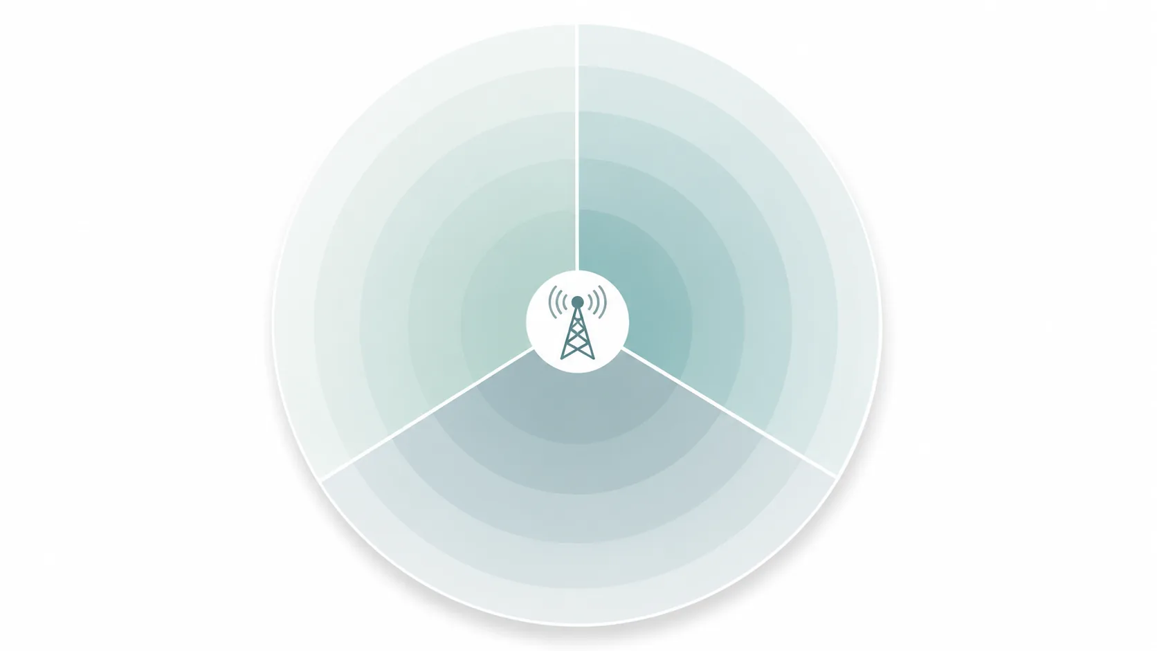
Hang three 120° panels at 0°, 120° and 240°, tilt each one down a few degrees, and the wedges close into a circle. Each sector runs its own radio or radio ports, so the same spectrum now serves three user groups at once instead of one. Concentrating energy into a 120° wedge rather than a full circle also buys roughly 5 dB of gain, which shows up as longer reach or better in-building penetration at the same transmit power. A 65° sector buys more.
Interference is the third win, and the least obvious one. Downtilt plus the sharp sector edge keeps energy inside the cell, which is what allows the next site down the road to reuse the same frequencies.
Planning then comes down to two numbers: sector count and overlap. Start with three sectors; it is the boring answer and usually the right one. Standards bodies agree — ITU-R Report M.2292, which defines the reference macro-cell parameters used in international sharing studies, assumes three sectors, 65° horizontal beamwidth and frequency reuse 1 across all of its macro deployments.
At the seams, aim for about 10–15% beam overlap. Less than that opens coverage gaps and drops handovers. Much more, and adjacent sectors waste capacity covering the same ground while interfering with each other.
Downtilt follows mast height, not habit
The same ITU-R reference parameters put macro downtilt between 3° and 10°, paired with antenna heights of roughly 20–30 m: the shorter the mast relative to the cell it serves, the steeper the tilt. ITU-R Recommendation M.2161-0 goes further for small sites, assuming 10° mechanical downtilt for a 6 m urban or suburban hotspot base station.
You can get to a starting angle with school geometry:
tilt ≈ arctan(antenna height above the users ÷ distance to the intended cell edge)
A 25 m mast aiming at a 400 m cell edge lands near 3.6°; a 6 m pole covering 100 m lands near 3.4°. Treat the result as the first setting to verify on site, not a final answer — terrain, clutter and the panel’s own elevation beamwidth all move it.

What the radiation pattern shows
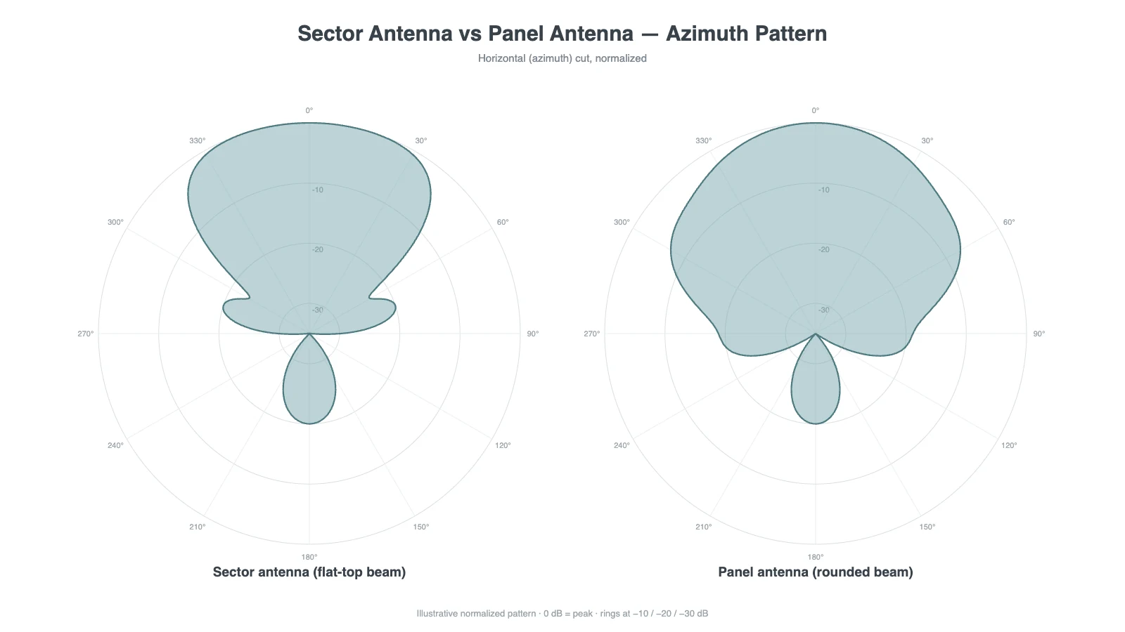
Put a sector panel, a general panel and an omni side by side on a pattern plot and the design intent is hard to miss:
| Pattern characteristic | Sector antenna | General panel antenna | Omnidirectional antenna |
|---|---|---|---|
| Azimuth beam | Flat-topped wedge (65°/90°/120°) with sharp roll-off | Variable, often rounded main lobe | Full 360° |
| Elevation beam | Narrow, high-gain, downtilted | Wider, downtilt optional | Narrow doughnut |
| Back lobe | Heavily suppressed | Moderate | N/A |
| Design goal | Tile sectors into a full cell | Cover one directional link | Cover everything equally |
The flat-topped azimuth beam is the signature. Signal strength stays even across the wedge and rolls off sharply at the edges, so adjacent sectors meet with predictable overlap instead of a mushy blend. For the theory behind these plots, panel antenna radiation pattern explained covers lobes, planes and beamwidth from the ground up.
The specs that decide whether the array works
A sector panel datasheet lists a dozen numbers. Nine of them can sink the deployment.
Start with beam geometry. Azimuth beamwidth fixes the sector count, and getting it wrong leaves gaps or heavy overlap that no amount of tilt tuning repairs. Gain trades against vertical beamwidth: a higher-gain panel reaches further but illuminates a thinner slice of ground, and on a tall mast an over-specified panel overshoots the users standing under it. Downtilt, whether fixed, adjustable or remote (RET), is the tool that actually fixes overshoot; adding gain to a badly tilted sector makes the problem worse.
Then the RF interface. Cellular MIMO expects dual-slant ±45° polarization, and a polarization mismatch quietly halves MIMO performance without raising a single alarm. Port count follows the MIMO order (2T2R, 4T4R), and the connector, typically 4.3-10 or N-female, has to match jumpers you can actually buy. VSWR tells you how much transmit power turns into heat instead of signal. Front-to-back ratio decides how politely back-to-back sectors coexist; a good 65° sector panel holds 25 dB or better, and anything much worse leaks noise into the opposite cell. That range is not a marketing figure: ITU-R’s own IMT base-station model assumes 65° beamwidths in both planes with a 30 dB front-to-back ratio, so 25–30 dB is the band standards work already assumes you have. Check gain and beamwidth at the band edges too, not just mid-band. Wideband panels drift, and a pattern that looks perfect at 2.5 GHz can open a handover gap at 2.7.
The mechanical spec gets skipped most often and should not be. A sector panel is a sail on a mast: confirm the wind survival rating, the bracket and the radome material against the site, especially for coastal and icing environments.
Six sectors is not double the capacity
The arithmetic looks free — twice the sectors, twice the spectrum reuse — and it never arrives intact. Three things eat into it:
- Overlap interference. Halving the beamwidth does not halve the interference, because the shoulders of each pattern still illuminate the neighbouring sector. Published sector-splitting gains vary widely with angle spread and user density, which is another way of saying the gain depends on your site, not on the sector count.
- Handover load. Six sectors mean twice as many sector borders for the same moving users, so signalling and handover failures rise where three sectors were quiet.
- Tower reality. Six panels means six brackets, more wind load and more azimuth alignment that has to be right. This is why the industry moved toward twin-beam panels that split one 65° beam into two narrower beams inside a single radome, keeping the antenna count and wind load of a three-sector site.
Practical rule: go past three sectors only when a capacity study, not a coverage map, says you need it — and budget for the tighter alignment and handover tuning that comes with it.
The mechanical and compliance checks that stop projects
These items rarely appear in antenna comparison articles, and they are the ones that delay builds.
- Structural load. A sector panel is a sail. In the US, antenna supporting structures and antennas are designed to ANSI/TIA-222, now at Revision I, which covers wind and ice loading for the structure, mounts and appurtenances. Adding six panels where three were planned is a structural change, not a shopping decision.
- Tower approvals. Structures generally taller than 200 feet, or sited near an airport, need FAA notification and FCC Antenna Structure Registration before construction. That paperwork, not antenna lead time, is often the critical path.
- Sector count is reportable. The FCC’s broadband data collection requires mobile providers to submit the number of sectors at each cell site, along with beamwidth, radiation pattern and azimuth, when coverage maps are verified. Your sector plan becomes a regulatory record, so document as-built azimuths and tilts.
Sector panel, general panel, or omni?
A sector antenna is a panel antenna, so the real question is the job. Tiling a site into wedges calls for purpose-built sector panels with matched beamwidth, downtilt and ±45° polarization. A single directional link or zone, say an FWA hub, a WiFi bridge or a point-to-multipoint feed, is better served by a general panel antenna, because without the flat-top constraint the beam can be shaped to fit the target. And when the site is small, users sit in every direction and capacity worries nobody, one omni beats an array on cost and simplicity; our omnidirectional vs directional antenna guide draws that line in more detail.
The expensive mistake is the middle case: sectorizing a site with general panels. Without controlled flat-top patterns and matched beamwidths the sectors overlap unevenly, handover suffers, and the capacity you paid for never arrives.
Mistakes that show up on real sites
A few failure patterns account for most underperforming sector deployments:
- Buying sector panels for a single point-to-point link. The flat-top beam exists for area coverage; a narrow-beam panel or dish serves one link better.
- Ignoring downtilt. On tall masts this is the top cause of overshoot and inter-cell interference, and it routinely gets misdiagnosed as “not enough gain”, after which someone orders higher-gain panels and makes it worse.
- Chasing maximum gain into a vertical beam so thin it misses the close-in users below the mast.
- Skipping the front-to-back check on a back-to-back array.
- Confirming polarization after installation instead of before ordering.
- Surveying only mid-band, then meeting the band-edge handover gap in production.
- Reading the −3 dB beamwidth as the sector boundary, then planning seams with no overlap.
- Adding sectors to a mast without rechecking wind load and mount capacity.
Specifying and ordering
A useful RFQ for a sectorized build names ten things: frequency band, layout (3×120°, 4×90° or 6×65°), per-sector gain target, downtilt type, polarization, port count, connector, mounting and mast height, environment (coastal, high-wind, icing) and quantity, whether pilot or rollout. With those lines a supplier can quote a matched set instead of a guess.
Our own sector panel range covers the common cellular bands with exactly these trade-offs in mind. The GL-DY2327S6515 is a 2.3–2.7 GHz 65° panel at 15 dBi; the GL-DY3338S6515 covers 3.3–3.8 GHz for mid-band 5G. Both are dual-slant ±45° with ≥25 dB front-to-back, and beamwidth or downtilt can be customized per project. The full range sits in the sector panel antenna category, and if you send the RFQ details above through a quote request, our engineering team will come back with a matched panel set for pilot or rollout.
Ask our AI antenna assistant. Enter a keyword or question for a free answer based on this article, Global RF Tech content, and general antenna/RF knowledge.
Do not submit confidential or personal information. Privacy Policy