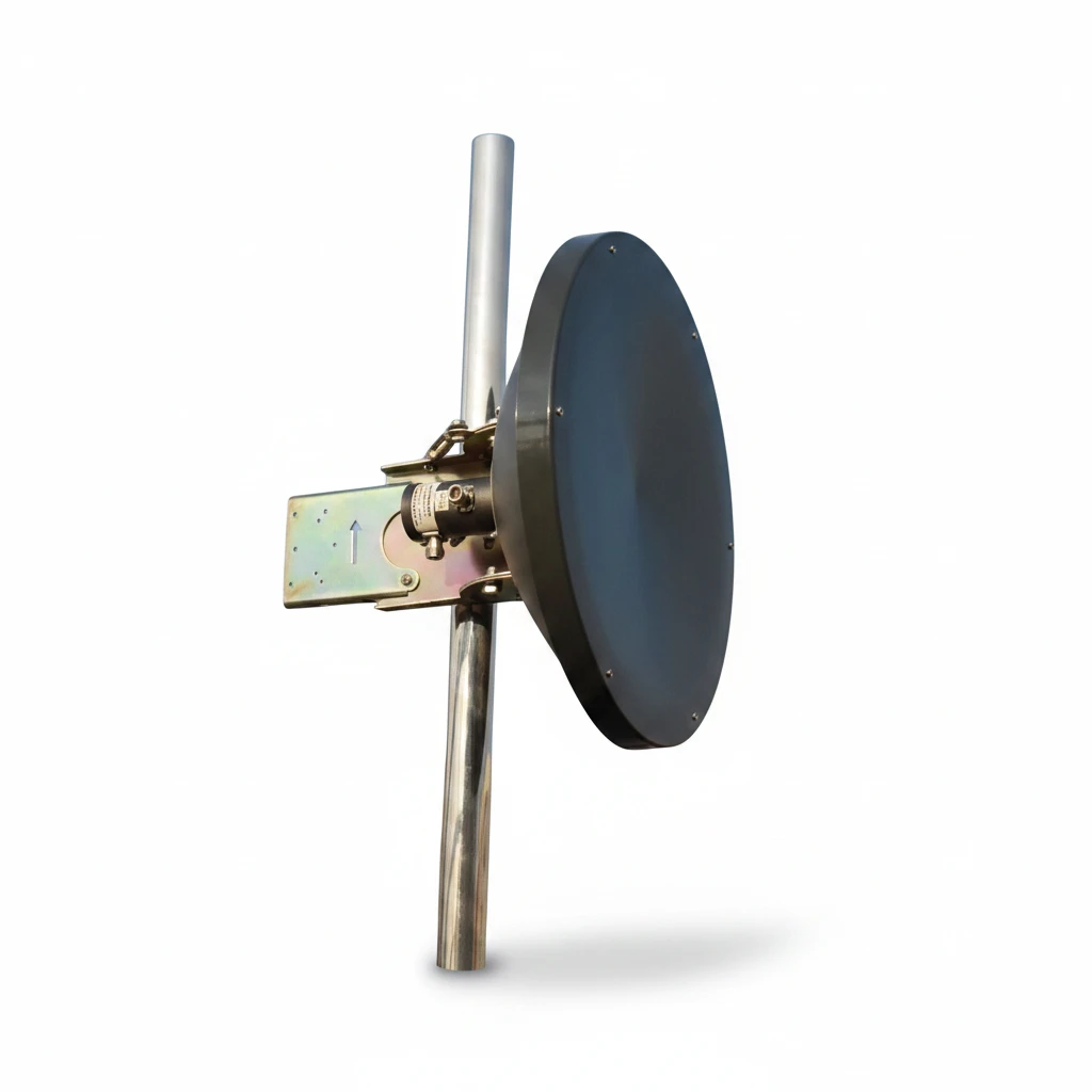
A parabolic antenna — usually called a dish antenna — uses a curved reflector to collect radio waves arriving from one direction and concentrate them onto a single small feed at the focus. Working the other way, it takes the power from that feed and throws it out as a narrow, tightly aimed beam. That one trick is what lets a 0.6 m dish deliver 28 dBi of gain and a 6° beam at 5 GHz, and it is why dishes dominate long point-to-point links, satellite ground stations and radar.
How a Parabolic Antenna Works
The reflector is a paraboloid, and a paraboloid has one useful geometric property: every ray arriving parallel to its axis bounces off the surface and passes through the same point, no matter where on the dish it lands. That point is the focus, and it is where the feed sits.
On receive, weak parallel wavefronts strike the whole reflector area and are funnelled into the feed, which converts them into current. On transmit the process runs backwards — the feed radiates toward the dish, and the reflector turns that spreading wave into a near-parallel beam. Nothing is amplified in the passive sense; the dish simply stops energy from going in directions you do not care about and redirects it toward the one direction you do.
Three parts do all the work:
- The reflector. A conductive parabolic surface, solid sheet or mesh. Ours are aluminium.
- The feed. A small antenna — horn, dipole or patch — held at the focal point.
- The support. The structure that keeps the feed exactly at the focus. Get this wrong by a fraction of a wavelength and the gain drops measurably.
Types of Parabolic Antenna
Dishes are usually classified by where the feed sits and what the surface is made of.
| Type | Feed position | Why you would pick it |
|---|---|---|
| Prime focus (axial) | Directly in front, on the axis | Simplest and most common. The feed and its support block a little of the aperture, costing a fraction of a dB. |
| Offset feed | Below or beside the axis, outside the beam path | No blockage, so slightly better efficiency. Familiar from home satellite dishes. |
| Cassegrain | At or behind the dish, via a convex sub-reflector | Keeps heavy electronics down at the back. Used on large earth-station antennas. |
| Gregorian | Same idea, concave sub-reflector | Tighter control of illumination on very large apertures. |
| Grid / mesh | Prime focus, open reflector | Far less wind load and weight. Only works when the mesh spacing is small relative to wavelength. |
| Shrouded | Any | A cylindrical shield around the rim cuts side and rear radiation on congested sites. |
Our published range is prime-focus solid dish, in single-polarised and dual-polarised versions. The dual-polarised units present two N-type ports so a 2×2 MIMO radio can use both chains.
How Parabolic Antenna Gain Is Calculated
Gain comes from aperture. The standard expression is:
where d = dish diameter, λ = wavelength, e = aperture efficiency
The squared term says gain rises with the square of diameter and falls with the square of wavelength — double the dish and you gain 6 dB; double the frequency and you gain another 6 dB from the same dish. Aperture efficiency e accounts for everything real: illumination taper, spillover past the rim, feed blockage, surface tolerance. Textbooks quote 50–60% for a well-built commercial dish.
A worked example using our own dishes
Formulas are easy to quote and harder to trust, so here it is run against two antennas whose specifications are published on this site.
| Model | Diameter | Frequency | Gain at 100% efficiency | Published gain | Implied efficiency |
|---|---|---|---|---|---|
| GL-DY5158V28 | ø0.6 m | 5.5 GHz | 30.8 dBi | 28 dBi | 53% |
| GL-DY5800V24A | ø0.4 m | 5.79 GHz | 27.7 dBi | 24 dBi | 43% |
Both land in or just under the expected band, which is what an honest datasheet looks like. The beamwidth prediction is even tidier. The rule of thumb for the 3 dB beamwidth of a circular aperture is:
For the 0.6 m dish at 5.5 GHz that predicts 6.4°; the datasheet says 6°. For the 0.4 m dish at 5.79 GHz it predicts 9.1°; the datasheet says 9°. When a published beamwidth and a published gain agree with the geometry like that, the numbers are measured rather than marketed — and that is worth checking on any dish you are quoted, from any supplier.
Quick sanity check for buyers: take the diameter and frequency, work out the 100%-efficiency gain, and compare it to the quoted figure. If the implied efficiency comes out above about 70%, the number is optimistic. If it comes out below about 35%, either the dish is inefficient or there is a typo in the datasheet.
Frequency Range and Why It Matters
A dish is a broadband device. The reflector itself is non-resonant — it does not care about frequency as long as it is large compared with the wavelength, and its surface is accurate compared with the wavelength. The feed sets the usable band, which is why the same reflector shape appears from roughly 1 GHz up past 100 GHz.
Two practical consequences follow:
- Below about 1 GHz a dish gets impractical. At 400 MHz the wavelength is 0.75 m, so a useful aperture would be several metres across. That is Yagi and log-periodic territory.
- Surface accuracy scales with frequency. A reflector good enough for 2.4 GHz may be too rough at 24 GHz. Millimetre-wave dishes need tighter manufacturing than microwave dishes of the same size.
Our published dishes cover 2200–2500 MHz and 5150–5850 MHz, with band-limited 5725–5850 MHz versions for ISM 5.8 GHz work where out-of-band rejection matters more than tuning range.
GNSS integration
Need help choosing a GNSS or patch antenna?
Tell us your device size, ground plane, constellation, cable and mounting requirements. We can help match active, passive or embedded GNSS antenna options.
Advantages of a Parabolic Antenna
- The highest gain per unit cost at microwave frequencies. Nothing passive beats a dish for turning aperture into forward gain.
- Very narrow beams. Our range goes down to 3.5°, which puts almost all the radiated power where you aimed it.
- Strong rejection off-axis. Published front-to-back figures here run from ≥20 dB to ≥40 dB. On a rooftop crowded with other links, that rejection is often worth more than the forward gain.
- Broadband by nature. Change the feed and the same reflector serves a different band.
- Fully reciprocal. The same dish transmits and receives with the same pattern, so a link budget is symmetrical.
Disadvantages and What They Actually Cost You
A dish is a specialist, and specialists are inflexible. These are the real trade-offs, not a list of reasons never to use one.
- Alignment discipline. A 3.5° beam means a couple of degrees of drift is a measurable loss. Dishes need a rigid mount and a proper alignment pass, and they need re-checking after storms.
- Wind load. Aperture is sail area. A 0.9 × 0.6 m grid loads a mast far harder than a 0.4 m dish, and the mast — not the antenna — is usually what fails first.
- Size and weight. Getting gain at 2.4 GHz means a physically large reflector. There is no way around the physics.
- No good for mobile or multipoint. If the far end moves, or clients arrive from many bearings, a narrow beam is a liability rather than an asset.
- Feed blockage on prime-focus designs. The feed and its supports sit in the beam and cost a fraction of a dB, plus slightly raised sidelobes.
- Weather effects at high frequency. Rain fade is a property of the link frequency rather than the dish, but accumulated snow or debris on the reflector will degrade a real installation.
When a Dish Beats a Yagi, a Panel or an Omni
| Situation | Better choice | Why |
|---|---|---|
| Fixed long-haul link, both ends known | Parabolic dish | Highest gain and narrowest beam available passively |
| Directional, but shorter hop or a mast that cannot take sail area | Yagi | Useful directivity with a fraction of the wind load and far easier aiming |
| Sector coverage, several clients in an arc | Panel or sector | A dish pointed at a sector wastes most of its advantage |
| Clients on every bearing, or a moving far end | Omnidirectional | A misaimed dish is worse than a modest omni |
| Below roughly 1 GHz | Yagi or log-periodic | Dish aperture becomes physically unreasonable |
The comparison people ask about most often is dish versus flat panel. A panel of the same physical area gives comparable gain and is far easier to mount, so at shorter ranges it usually wins on practicality. The dish pulls ahead once you need the last several dB, because you can keep growing a reflector long after a panel array has become expensive and lossy to feed. If you are weighing coverage shape rather than raw gain, our omnidirectional vs directional comparison covers that trade-off in more detail.
Frequently Asked Questions
What is a parabolic antenna used for?
Fixed point-to-point microwave links, satellite ground stations, radar, and radio astronomy. Anywhere both ends are in known positions and the priority is reach rather than coverage.
What are the disadvantages of parabolic antennas?
They are physically large, they present significant wind load, they demand accurate alignment and a rigid mount, and their narrow beam makes them unsuitable for mobile or multipoint use. Prime-focus designs also lose a fraction of a dB to feed blockage.
What frequency would a parabolic dish antenna use?
Practically from about 1 GHz up past 100 GHz. Below 1 GHz the required aperture becomes unreasonable. Our published dishes cover 2200–2500 MHz and 5150–5850 MHz.
Which is better, a Yagi antenna or a parabolic antenna?
Neither is better in general. A dish gives more gain and a narrower beam; a Yagi is lighter, cheaper, far more tolerant of aiming error and much kinder to a mast. Choose the dish when the link budget demands it, the Yagi when it does not.
Which is better, a flat plate or a parabolic antenna?
At equal physical area they are close in gain, and the flat panel is easier to mount and less affected by wind. The dish wins when you need very high gain, because a reflector scales up more gracefully than a panel array.
What is the gain of a parabolic antenna?
It depends on diameter, frequency and aperture efficiency. Commercial dishes typically run 20–45 dBi, and very large earth-station antennas exceed 50 dBi. Our published range is 17–28 dBi across 2.4 and 5 GHz.
Need help sizing a dish for your link?
Send us the band, the path length, the radio and port count, and what you are mounting to. We will come back with the matching dish, the connector and jumper detail, and a sample or production quote.
Ready to specify a product?
Get product suggestions and quotation details for your application.
Tell us your device size, ground plane, constellation, cable and mounting requirements. We can help match active, passive or embedded GNSS antenna options.
Ask our AI antenna assistant. Enter a keyword or question for a free answer based on this article, Global RF Tech content, and general antenna/RF knowledge.
Do not submit confidential or personal information. Privacy Policy