

A whip antenna is a straight, usually flexible conductor connected at
one end to a radio. Most familiar whips operate as monopoles: the whip
is the driven element, while a conductive vehicle body, equipment
chassis, PCB ground or counterpoise provides the return path. This
simple structure makes whip antennas practical for handheld radios,
vehicles, gateways and other equipment that needs broad coverage around
the antenna.
The shape is easy to recognize, but length alone does not tell you
whether a whip will work. Frequency range, electrical length, ground
plane, matching, connector, mounting position and the surrounding
structure all affect the installed result.
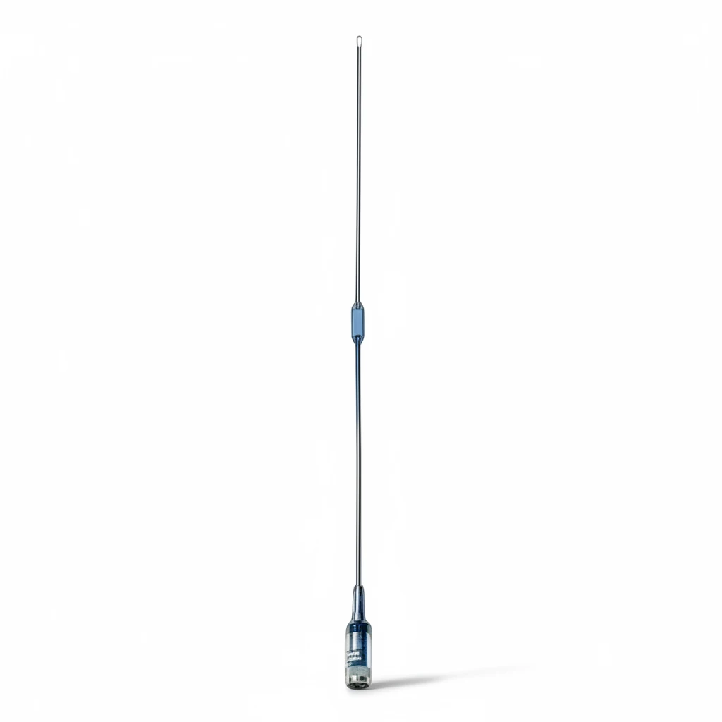
How Does a Whip Antenna Work?
RF current on the conductor produces an electromagnetic field. In a
conventional quarter-wave monopole, the conductive surface below the
whip acts as the other part of the antenna system. The combination
resembles half of a dipole above an electrical image.
An ideal vertical monopole has vertical polarization and broad
coverage around the horizon. “Omnidirectional” describes the azimuth
pattern; it does not mean equal radiation in every three-dimensional
direction. The idealized pattern has little radiation along the whip’s
axis, and a real vehicle, enclosure or mast distorts the pattern
further. The Antenna
Theory monopole reference illustrates how a finite ground plane
changes the impedance and elevation pattern.
This is why an antenna that measures well on a large metal roof can
behave differently on a plastic enclosure. The mounting structure is not
merely mechanical hardware—it can be part of the RF design.
How Long Should a Whip
Antenna Be?
The free-space wavelength is:
wavelength (m) = 300 / frequency (MHz)
A first quarter-wave estimate is therefore:
quarter-wave length (m) = 75 / frequency (MHz)
| Frequency | Free-space quarter-wave estimate |
|---|---|
| 150 MHz | 0.50 m |
| 350 MHz | 0.214 m |
| 433 MHz | 0.173 m |
| 868 MHz | 0.086 m |
| 915 MHz | 0.082 m |
| 2.4 GHz | 0.031 m |
These numbers are starting estimates, not manufacturing cut lengths.
Conductor diameter, protective materials, loading coils, matching
components, connector geometry, enclosure and nearby metal can all
change the resonant point. A final design should be checked in the
intended installation with suitable RF measurements.
A physically short whip can be made electrically longer with loading.
That helps when clearance is limited, but it creates a trade-off:
reduced size may affect efficiency, bandwidth or matching. “Shorter” is
therefore a mechanical benefit, not automatic evidence of equal RF
performance.
Common Whip Antenna Types
Straight quarter-wave whip
This is the simplest reference design. It is attractive when the
natural length is practical and a suitable ground plane is available. It
often provides a useful balance of simplicity, bandwidth and
efficiency.
Loaded whip
A loaded whip uses an inductive or other matching structure to
achieve the required electrical behavior in less physical length. It is
useful when a full-size element will not fit, but the specific bandwidth
and efficiency must be evaluated rather than assumed.
Flexible or rubber-duck
antenna
A rubber-duck antenna is a compact, protected form commonly used on
handheld equipment. It prioritizes size and mechanical resilience. If
range or efficiency is the main constraint, compare it with a longer
whip under the same radio and test conditions. See the RFTECH rubber duck
antenna category for the adjacent product format.
Magnetic-mount mobile whip
A magnetic base makes a vehicle antenna removable and easy to
reposition. It still needs an appropriate conductive mounting surface
and a sensible cable route. Placing it on a small metal bracket or a
nonconductive roof is not equivalent to mounting it near the center of a
suitable metal surface.
Connector-mounted handheld
whip
These antennas attach directly to a radio or terminal through
connectors such as SMA, BNC or TNC. The radio body and internal ground
can become part of the antenna system, so performance should be
evaluated on the target device—not only on a generic fixture.
Telescopic whip
A telescopic element provides adjustable physical length and compact
storage. It is useful for receivers, test setups and tunable
applications, but the selected extension length must still correspond to
the intended frequency and matching condition.
Does a Whip Antenna
Need a Ground Plane?
It depends on the electrical design.
A conventional quarter-wave monopole normally relies on a conductive
ground plane or counterpoise. On a vehicle, the metal body can provide
that function. On a handheld radio, the chassis, PCB ground and even
interaction with the user can influence the result. A mast installation
may use radial conductors as an artificial ground plane.
A half-wave, dipole-based or specifically designed no-ground-plane
antenna follows a different current-return arrangement. Do not assume
that a loading coil removes the need for a return path; loading changes
electrical length and matching, not the basic requirement to understand
where RF current returns.
The practical question is not simply “Does this antenna need ground?”
Ask instead:
- What antenna topology is being used?
- What conductive structure was present during tuning?
- Will the production installation reproduce that structure?
- What happens to matching and efficiency when the antenna is
installed on the real equipment?
How to Choose a Whip Antenna
1. Define the complete
frequency range
List every required transmit and receive band. A model that resonates
near one frequency may not cover the complete channel plan with
acceptable matching.
2. Identify the radio and
installation
State whether the antenna connects to a handheld radio, vehicle
radio, gateway, enclosure or remote cable assembly. The same frequency
can require different mechanical and RF solutions.
3. Document the available
ground plane
Record the material, dimensions and position of the conductive
surface. If the roof or enclosure is fiberglass or plastic, say so
before selecting a conventional magnetic-mount monopole.
4. Set the size limit
Give the maximum installed height, storage requirement and clearance
risk. Then compare a natural-length element with a loaded alternative
instead of specifying a short whip without an RF trade-off
discussion.
5. Confirm the connector and
mount
Connector family, gender and mounting geometry must match the radio
or cable assembly. For a mobile installation, decide whether the antenna
must be removable, permanent, foldable or impact tolerant.
6. Check the environment
and cable path
Nearby metal, cable length, sharp bends, vibration and exposure can
affect both integration and RF performance. Keep the cable arrangement
consistent with the configuration used for validation.
7. Ask for
evidence that matches the application
Useful evidence can include a datasheet, dimensional drawing, VSWR or
return-loss plot, radiation pattern, installation instructions and
measurements from a representative ground plane. A single peak-gain
number cannot predict system range.
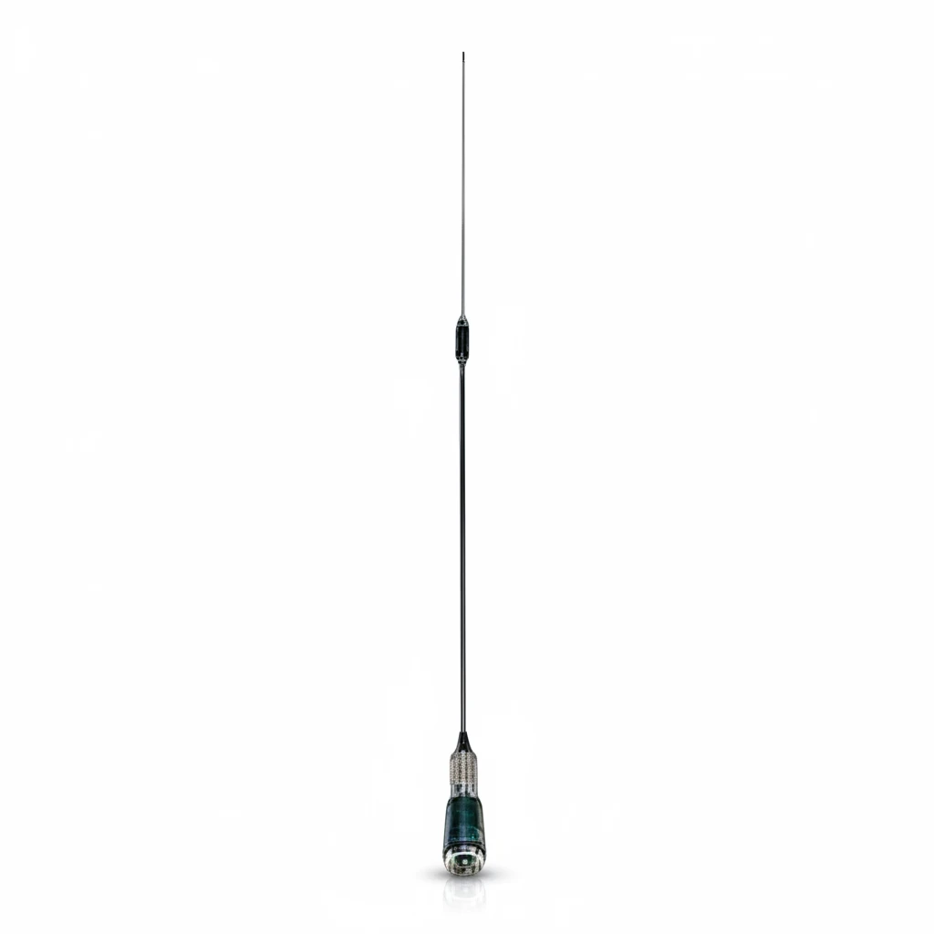
RFTECH’s published examples show how these decisions change the
product. The GL-DYC150I
VHF mobile antenna covers 134–173 MHz with a 96 cm element, UHF Male
connector and magnetic mount. The GL-DYX150S
terminal antenna covers the same published band in a 12 cm SMA Male
handheld format. They share a frequency range but solve different
installation problems.
Common Selection Mistakes
- Choosing by length alone. Two whips of similar
length can be tuned for different bands or use different loading. - Ignoring the ground plane. A good bench result may
not survive installation on a small or nonconductive surface. - Treating gain as range. Link distance also depends
on power, receiver sensitivity, losses, height, terrain, interference
and orientation. - Using the wrong connector description. SMA and
reverse-polarity SMA, or male and female interfaces, are not
interchangeable. - Testing the antenna away from the final device.
Enclosure and cable effects can shift matching. - Assuming the shortest model is equivalent.
Compactness usually involves an RF trade-off that should be
measured.
When Is a Whip Antenna
the Wrong Choice?
A whip is not the default answer when the link needs directional
coverage, very high isolation, low visual profile, multi-element MIMO
geometry or operation without a predictable return structure. A panel,
Yagi, dipole, PCB antenna, puck or other format may fit the installation
better.
The right comparison is based on the complete radio system, not the
antenna name.
Frequently Asked Questions
What is the range of a whip
antenna?
There is no fixed range. It depends on frequency, antenna efficiency
and pattern, radio power, receiver sensitivity, cable loss, mounting
height, terrain, interference and the installation ground plane.
Is a longer whip always
better?
No. The element must be electrically appropriate for the operating
band. Extra length can change impedance and pattern rather than improve
the link.
What is
the difference between a whip and a monopole?
“Whip” describes the familiar flexible rod form. “Monopole” describes
an electrical antenna topology. Many whips are monopoles, but not every
product called a whip has the same electrical design.
Can a whip antenna be
mounted on plastic?
It can be physically mounted there, but a conventional
ground-dependent monopole may not perform as intended without a suitable
counterpoise or a design made for that installation.
Select the
Antenna as Part of the Installation
Whip antennas are simple only when the RF and mechanical conditions
are already understood. Start with frequency, then define the ground
plane, size, connector, mount and installation environment. Validate the
final configuration rather than relying on length or gain alone.
Browse the RFTECH Whip Antennas
category or submit
your project requirements. Include the operating band, equipment,
available ground plane, size limit, connector, mount, environment and
quantity so the team can review the correct antenna format.
Ask our AI antenna assistant. Enter a keyword or question for a free answer based on this article, Global RF Tech content, and general antenna/RF knowledge.
Do not submit confidential or personal information. Privacy Policy




