A panel antenna radiation pattern is a map of where the antenna sends and receives radio energy. Read it correctly and you can predict coverage, reach, and interference before any hardware goes up. The radiation pattern of a directional panel antenna shows a strong main lobe pointing forward and a suppressed back lobe, which is exactly why a panel antenna covers a defined area instead of radiating in every direction. This guide explains how to read the pattern, what E-plane and H-plane mean, and how the pattern decides which antenna fits your link.
What a radiation pattern actually shows
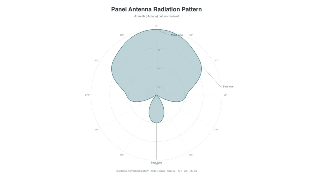
A radiation pattern is a plot of relative signal strength versus direction, usually drawn as a polar graph. The shape tells you where the antenna is “loud” and where it is “quiet.” Three features matter most:
- Main lobe: the direction of maximum radiation. This is where the antenna does its work.
- Side lobes and back lobe: smaller lobes pointing in other directions. They can cause or pick up interference, so smaller is usually better for a directional link.
- Nulls: directions where radiation drops to near zero.
Because an antenna radiates in three dimensions, a single 2D plot is only one slice. That is why datasheets show at least two cuts: the E-plane and the H-plane.
E-plane and H-plane: the two views you need
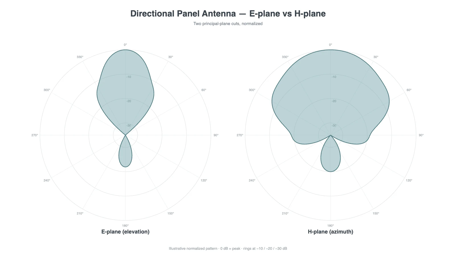
A full pattern is 3D, but engineers describe it with two perpendicular slices:
- E-plane: the plane containing the electric field and the direction of maximum radiation. For a vertically polarized antenna, this is the vertical (elevation) cut.
- H-plane: the plane containing the magnetic field, perpendicular to the E-plane. For the same antenna, this is the horizontal (azimuth) cut.
Together, the E-plane and H-plane plots tell you the beamwidth in both directions, so you know whether the antenna covers a tall-and-narrow slice, a wide flat fan, or a focused pencil beam. When you request a datasheet, ask for both cuts measured across the operating band, since the pattern can change with frequency.
Key terms that read the pattern for you
| Term | What it tells you |
|---|---|
| Beamwidth (HPBW) | The angular width where power is within 3 dB of the peak, i.e. the usable coverage angle |
| Gain (dBi) | How much the antenna concentrates energy in the main lobe vs an isotropic radiator |
| Front-to-back ratio | How well the antenna rejects energy from behind; higher is better for directional links |
| Side-lobe level | How strong the unwanted lobes are relative to the main lobe |
| Polarization | The orientation of the radiated field (vertical, horizontal, or dual/slant) |
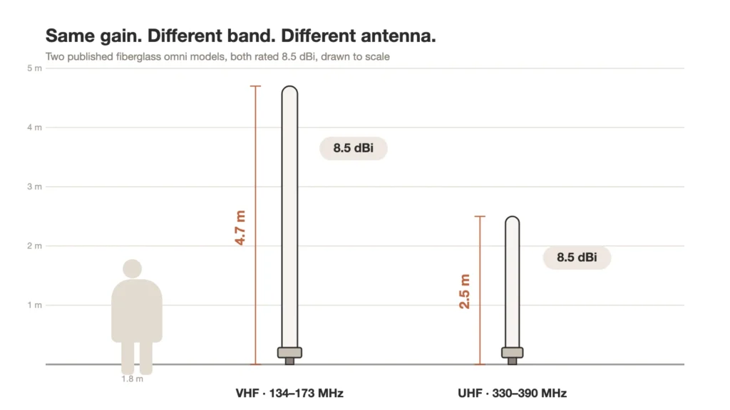
Gain and beamwidth are linked: for a given antenna type, a narrower beam concentrates energy and raises gain, while a wider beam lowers it. There is no free lunch: higher gain means a tighter beam that must be aimed more carefully.
Directional vs omnidirectional patterns
The single biggest split in radiation patterns is directional versus omnidirectional.
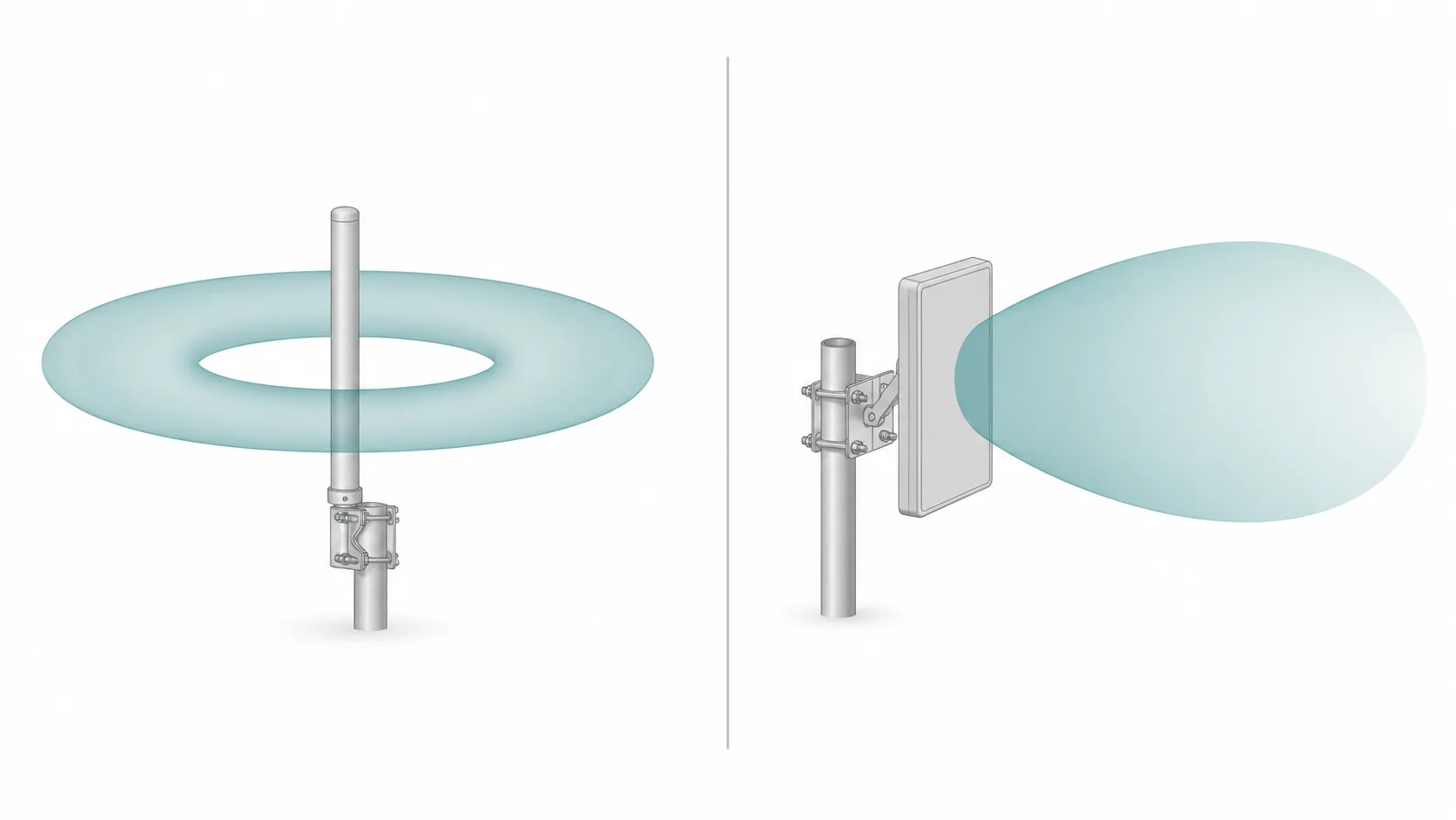
- Omnidirectional antenna: radiates roughly 360° in the horizontal plane, like a donut seen from above. It covers all directions at lower gain. Use it when clients surround the site.
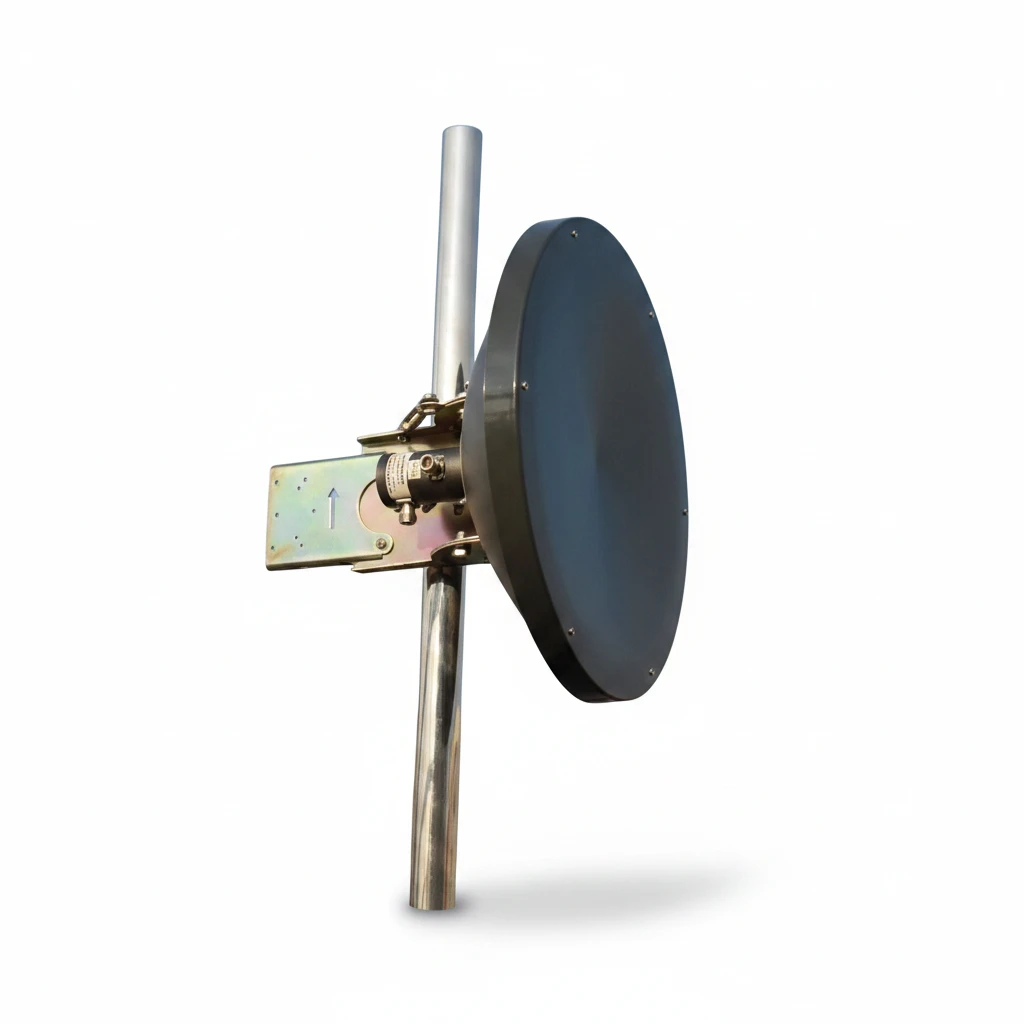
- Directional antenna: concentrates energy in one direction with higher gain and a defined beamwidth. Panel, sector, Yagi, and dish antennas are all directional. Use it when you know where the traffic is.
A panel antenna is firmly in the directional camp. Its reflector pushes energy forward and suppresses the back lobe, producing a main lobe aimed at the target area and very little radiation behind it.

If you need the broader choice between full-circle coverage and a focused beam, read the omnidirectional vs directional antenna radiation patterns guide. This page stays focused on panel antenna plots, E-plane/H-plane cuts, beamwidth, side lobes, and other directional pattern terms.
The radiation pattern of a directional panel antenna
A directional panel antenna’s pattern has a clear forward main lobe, a small back lobe, and a beamwidth set by the element layout. Designers shape it for the job:
- A wide-beam panel spreads coverage across a zone or a cluster of clients.
- A narrow-beam panel concentrates energy toward a more distant target for a focused link.
- A sector panel uses a flat-topped azimuth beam and a narrow elevation beam so multiple antennas tile into full cell coverage.
This is why “panel antenna” covers many shapes: the flat aperture lets designers tune the E-plane and H-plane beamwidth almost independently. The same physics governs a microstrip patch antenna radiation pattern, since a panel is often a patch array behind a reflector. To see how the panel pattern stacks up against other directional types, compare the radiation patterns of a panel antenna vs a Yagi antenna and the sector antenna pattern vs a panel antenna.
Interference environment
Need an antenna matched to a high-interference project?
Tell us the frequency range, installation space and interference scenario. We can suggest suitable anti-jamming or specialty antenna options.
How to use the pattern when choosing an antenna
- Start with coverage shape. Decide whether you need a point, an area, one sector, or a full 360° site. For a sectorized antenna layout, sketch the sector split first — for example 3 × 120° or 6 × 65° — then choose the antenna beamwidth.
- Match beamwidth to the target. A target that moves, sways, or spans a wide area needs a wider beam; a fixed distant point can use a narrow one.
- Check front-to-back and side lobes if interference is a concern.
- Confirm polarization matches your radio, especially for MIMO links that need dual polarization.
- Read the pattern across the band, not just at the center frequency.
Common misreadings to avoid
- Treating gain as range. Gain only helps in the direction of the main lobe. Off-axis, a high-gain antenna can be worse than a low-gain one.
- Ignoring the vertical cut. A great azimuth pattern with the wrong elevation beam or downtilt can overshoot or undershoot the target entirely.
- Assuming one plot is the whole story. Always read both E-plane and H-plane.
FAQ
Do panel antennas emit RF 360 degrees?
No. A panel antenna is directional. It focuses RF energy in one direction (a forward main lobe) and its reflector suppresses radiation to the rear, so it does not emit 360°. For controlled full-site coverage, use multiple sector panels in a sectorized antenna layout, or choose an omnidirectional antenna when the site is simple and low capacity.
What is the difference between E-plane and H-plane?
The E-plane is the slice of the radiation pattern aligned with the antenna’s electric field and main beam (the elevation cut for a vertically polarized antenna), while the H-plane is the perpendicular slice (the azimuth cut). Reading both tells you the beamwidth in each direction.
What does beamwidth tell me about an antenna?
Beamwidth (half-power beamwidth) is the angle over which the antenna radiates within 3 dB of its peak. It is effectively the usable coverage angle. A narrow beamwidth means high gain and a focused beam that must be aimed precisely; a wide beamwidth covers more area at lower gain.
Is higher antenna gain always better?
No. Higher gain comes from a narrower beam, so it only helps if you can aim the antenna accurately and the target stays inside the beam. For wide-area coverage or moving mounts, a lower-gain, wider-beam antenna often performs better.
Related guides
- Panel Antenna vs Yagi Antenna: Radiation Patterns and How to Choose
- Sectorized Antennas: 3×120°, 4×90° and 6×65° Layouts
- Panel antenna types and models
Conclusion
A radiation pattern tells you where an antenna’s energy goes, and that, more than any single gain figure, decides whether an antenna fits your link. Learn to read the main lobe, beamwidth, front-to-back ratio, and the E-plane/H-plane cuts, and you can choose between directional and omnidirectional, and between panel, sector, and Yagi designs, with confidence.
Once you know the coverage shape you need, the next step is matching it to a specific antenna. See the panel vs Yagi and panel vs sector comparisons, or browse directional panel antennas to find a model with the pattern your deployment requires.
Ready to specify a product?
Get product suggestions and quotation details for your application.
Tell us the frequency range, installation space and interference scenario. We can suggest suitable anti-jamming or specialty antenna options.