

Antenna gain describes how strongly an antenna concentrates RF energy in a particular direction compared with an ideal reference. A higher-gain antenna does not create extra power—it redistributes the power you feed it, narrowing the beam in some directions and reducing radiation in others.
In practice, gain combines two concepts:
- Directivity (D): how focused the radiation pattern is
- Efficiency (η): how much input power is actually radiated (vs. lost as heat, mismatch, etc.)
A common relationship is:
G = ηD- G = gain (linear power ratio)
- η = efficiency (0 to 1)
- D = directivity (linear)
Because efficiency is always less than or equal to 1, two antennas can have the same directivity but different gain if one has higher losses. Gain is usually reported in dBi (decibels relative to an isotropic radiator).
Radiation patterns of isotropic, dipole, and high-gain directional antennas
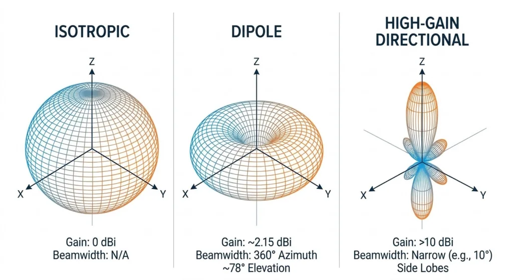
The Basic Gain Formula (Power Ratio)
If you are comparing radiation in a specific direction against a reference, the simplest expression is a power ratio:
G(dB) = 10 log₁₀(P₂ / P₁)- P₂ = power in the direction of interest (from the antenna under test)
- P₁ = power in the same direction from the reference radiator
- G(dB) = gain in decibels
For an isotropic reference, the result is typically stated as dBi.
Gain From Directivity and Efficiency
If directivity and efficiency are known (from simulation, a datasheet, or measured patterns), multiply them:
G = ηD
G(dBi) = 10 log₁₀(ηD)
Example: directivity = 8, efficiency = 0.70
G = 0.70 × 8 = 5.6
G(dBi) = 10 log₁₀(5.6) = 7.48 dBi
Rounded: 7.5 dBi
Gain From Aperture Area and Wavelength (Dish/Horn/Aperture Antennas)
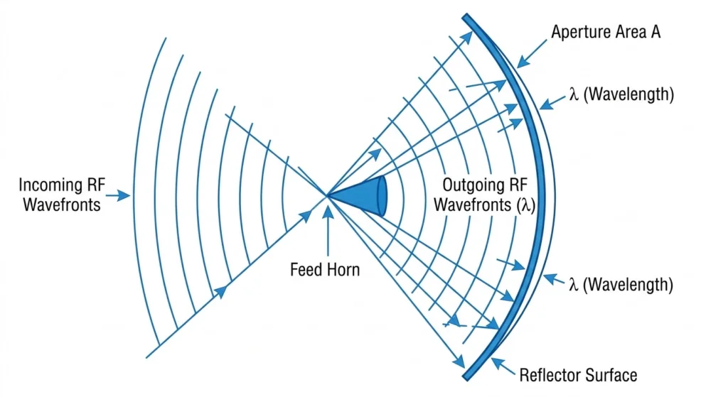
Parabolic dish antenna geometry: aperture area A, wavelength λ, feed horn, and reflector surfac
For parabolic dishes, horns, and other aperture antennas, gain can be estimated from physical area and wavelength:
G = 4πηA / λ²
G(dBi) = 10 log₁₀(4πηA / λ²)- η = aperture efficiency
- A = physical aperture area (m²)
- λ = wavelength (m)
Example: A = 2 m², η = 0.60, λ = 0.1 m
G = 4π × 0.60 × 2 / 0.01 = 1507.96
G(dBi) = 10 log₁₀(1507.96) = 31.78 dBi
Rounded: 31.8 dBi
This relationship also explains why higher frequencies (smaller λ) can achieve higher gain for the same physical aperture.
Gain From Antenna Factor (AF)
In EMC/measurement contexts, calibration data is sometimes provided as antenna factor (AF) rather than gain. A commonly used conversion is:
G(dBi) = -AF + 20 log₁₀(f) - 29.8- AF = antenna factor (dB/m)
- f = frequency (MHz)
- 29.8 = constant for 50-ohm systems (commonly used in this conversion)
Example: AF = 20 dB/m, f = 1000 MHz
G(dBi) = -20 + 60 - 29.8 = 10.2 dBiResult: 10.2 dBi
Note: Different lab conventions and system assumptions can change constants slightly. If you are working from calibration certificates, follow the specific formula provided by the lab when available.
dBi vs dBd
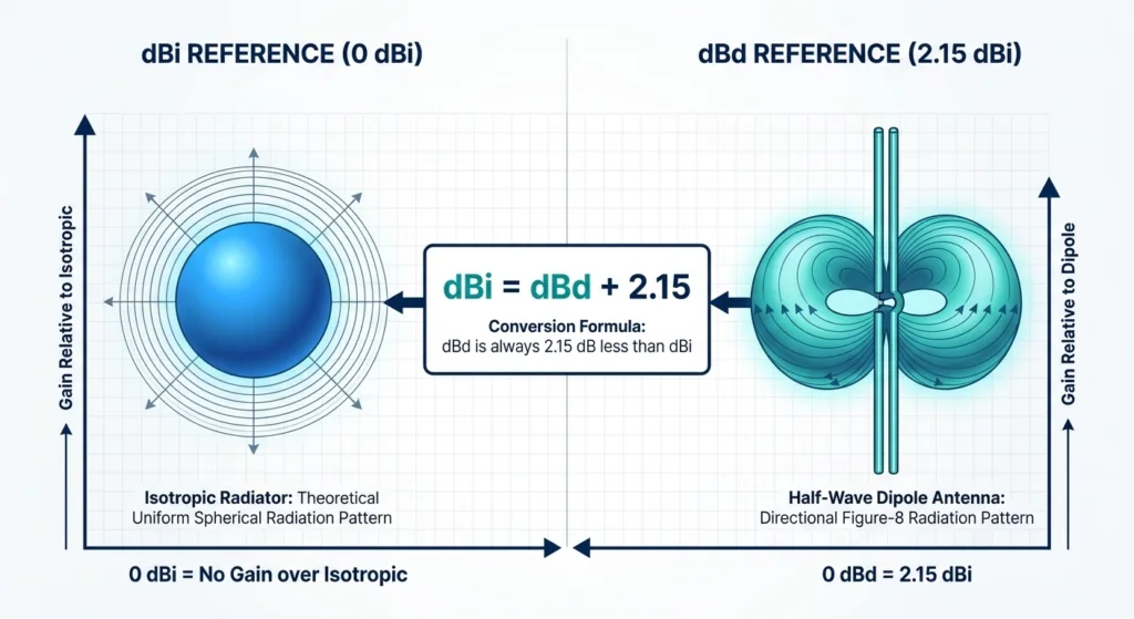
dBi vs dBd reference comparison with conversion formula dBi = dBd + 2.15
dBi and dBd use different references:
- dBi: referenced to an isotropic radiator (ideal point source)
- dBd: referenced to a half-wave dipole
A half-wave dipole has 2.15 dB of gain over an isotropic radiator, so:
dBi = dBd + 2.15
dBd = dBi - 2.15
Examples:
- 8 dBi = 5.85 dBd
- 0 dBd = 2.15 dBi
- 5 dBd = 7.15 dBi
When comparing antennas, always convert to the same reference before judging which one is “higher gain.”
Can You Calculate Gain From Field Strength?
Yes, but results are often unreliable outside controlled conditions. Reflections, ground effects, polarization mismatch, nearby objects, and near-field measurement errors can significantly distort the calculated gain.
If you are measuring, ensure you are in the far field. A common far-field distance estimate is:
R ≥ 2D² / λ- R = far-field distance
- D = largest antenna dimension
- λ = wavelength
Directional link planning
Need gain and beamwidth matched to your link?
Tell us the link distance, target band, mounting height and coverage direction. We can help compare Yagi, panel, sector and LPDA antenna options.
Common Mistakes
- Confusing antenna gain with amplifier gain. Antennas do not add power; they redistribute radiated energy.
- Ignoring efficiency. Directivity alone is not gain—losses can reduce real-world performance.
- Mixing dBi and dBd. They differ by 2.15 dB; convert before comparing.
- Assuming physical aperture equals effective aperture. Real antennas have aperture efficiency < 1.
- Measuring too close. Near-field measurements can produce misleading “gain” numbers.
- Treating datasheet gain as installed gain. Feedline loss, mismatch, mounting hardware, and nearby objects can reduce system performance.
- Forgetting gain depends on direction. “10 dBi” is typically peak gain; off-axis gain can be much lower.
Picking the Right Formula
| What you know | Formula |
|---|---|
| Directivity and efficiency | G = ηD |
| Power ratio | G(dB) = 10 log₁₀(P₂ / P₁) |
| Dish or horn dimensions | G = 4πηA/λ² |
| Antenna factor and frequency | G(dBi) = -AF + 20 log₁₀(f) – 29.8 |
| Datasheet in dBd | Add 2.15 to get dBi |
Worked Example
Suppose you are designing a directional antenna for a wireless link:
- Directivity = 12
- Radiation efficiency = 80%
- Answer required in dBi
Linear gain:
G = 0.80 × 12 = 9.6Convert to dBi:
G(dBi) = 10 log₁₀(9.6) = 9.82 dBiRounded: 9.8 dBi
Getting More Gain
Higher gain typically means a narrower beamwidth. That can improve a fixed point-to-point link but may reduce coverage in mobile or indoor environments.
For antenna-specific gain behaviour, see patch antenna gain and LPDA directional gain.
Common ways to increase gain include:
- Increasing aperture size (larger antenna)
- Improving efficiency (lower conductor/dielectric losses, better matching)
- Using more directional structures (Yagi, horn, patch array, parabolic dish)
- Optimizing dimensions for the operating frequency
- Reducing system losses (shorter feedlines, better connectors, cleaner installation)
FAQ
What’s the simplest formula?
G(dB) = 10 log₁₀(P₂/P₁), a power-ratio comparison to a reference radiator.
What’s the most practical for design work?
G = ηD converted to dBi, because it captures both directionality and loss.
dB or dBi?
Always specify the reference. “dB” alone is ambiguous.
Does higher gain mean more power?
No. It means more radiation in certain directions and less in others.
Conclusion
Choose the calculation method based on the information available:
- Directivity and efficiency → G = ηD
- Physical aperture and wavelength → G = 4πηA/λ²
- Lab calibration data → use antenna-factor conversion as specified
When reporting results, state whether the gain is dBi or dBd, and convert when comparing antennas.
Related reading: if you are comparing indoor signal behavior in real buildings, see our guide to distributed antenna systems (DAS).
Ready to specify a product?
Get product suggestions and quotation details for your application.
Tell us the link distance, target band, mounting height and coverage direction. We can help compare Yagi, panel, sector and LPDA antenna options.
Ask our AI antenna assistant. Enter a keyword or question for a free answer based on this article, Global RF Tech content, and general antenna/RF knowledge.
Do not submit confidential or personal information. Privacy Policy




