
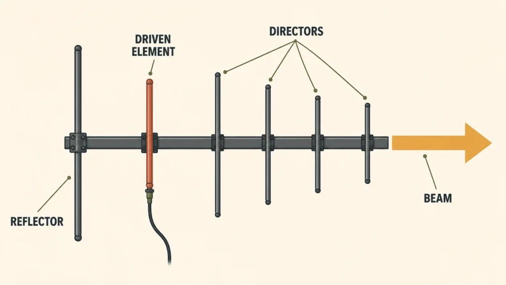
A Yagi antenna — properly a Yagi-Uda antenna — is a directional antenna that arranges several parallel elements along a boom to focus radio energy in one direction. That focus is the whole point: instead of spreading power evenly like an omnidirectional whip, a Yagi concentrates it into a beam, which raises gain, extends point-to-point range, and rejects interference arriving from other directions. This guide covers the parts, the working principle, the radiation pattern, and — because it is the question buyers actually ask — what a Yagi antenna is used for and when you should pick one over other directional designs.
What is a Yagi (Yagi-Uda) antenna?
The design dates to 1920s Japan, where Shintaro Uda and Hidetsugu Yagi showed that placing passive metal rods near a driven dipole could steer its radiation into a beam. The result is an end-fire array: all elements sit parallel to each other along a central boom, and the beam fires off the end of the boom, through the shortest elements.
Only one element is wired to anything. The rest shape the beam through electromagnetic coupling alone, with no feed network or powered parts, and that simplicity is why the same basic design still serves rooftop TV reception, industrial telemetry links, and amateur radio a century later.
Parts of a Yagi antenna
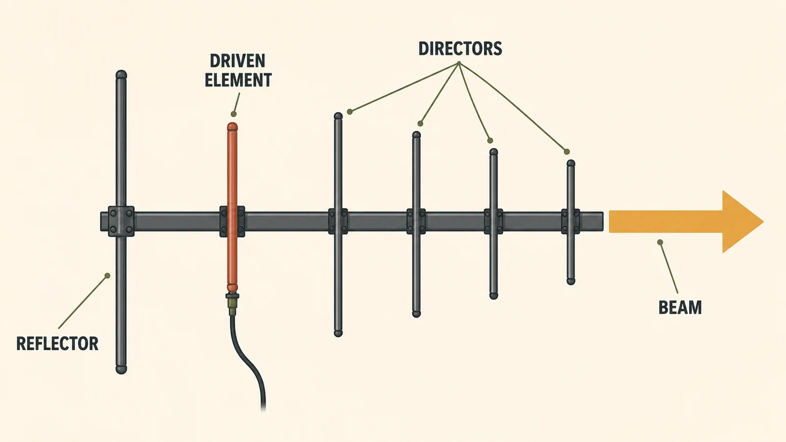
- Driven element. The only element connected to the coax — usually a half-wave dipole (often a folded dipole, whose higher native impedance simplifies matching). It transmits and receives the actual signal.
- Reflector. A single rod behind the driven element, cut roughly 5% longer. It re-radiates energy with a phase that cancels backward radiation and reinforces the forward beam.
- Directors. One or more rods in front of the driven element, each slightly shorter than the last. They progressively pull the beam forward and tighten it.
- Boom. The spine that holds every element at its designed spacing. Element positions are part of the electrical design, not just mechanics — which is why a bent boom degrades performance.
How a Yagi antenna works
The passive elements are the trick. Radio waves from the driven element induce currents in the reflector and directors; those currents re-radiate with phase shifts set by each element’s length and spacing. Elements longer than resonance behave inductively, shorter ones capacitively, and the designer exploits this so that every element’s re-radiation adds constructively toward the front of the antenna and destructively toward the back.
Practical consequences of that mechanism:
- More directors, more gain — with diminishing returns. A 3-element Yagi delivers roughly 7–9 dBi; doubling the boom length buys about 3 dB each time, so a 12-element design might reach 14–15 dBi. Past that, boom length grows faster than gain.
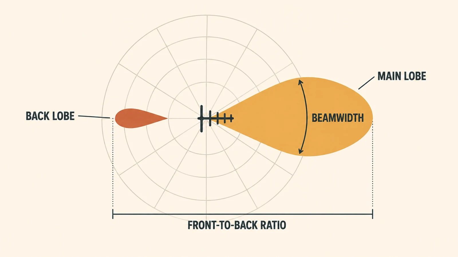
- Gain buys narrower beamwidth. A 7 dBi Yagi covers around 60–70° horizontally; a 15 dBi design nearer 30°. Higher gain means more precise aiming — and more sensitivity to mast twist and wind.
- Bandwidth is inherently narrow. The phase relationships only hold near the design frequency; a typical Yagi covers a few percent of bandwidth. That is fine for a licensed telemetry channel, limiting for wideband use — where a log-periodic (LPDA) is usually the better tool.
Yagi radiation pattern and key specs
The pattern is a single forward lobe with a small back lobe and minor side lobes. When reading a Yagi datasheet, these numbers matter:
| Spec | Typical range | What it tells you |
|---|---|---|
| Gain | 7–15 dBi | Forward concentration of energy; drives range |
| Beamwidth (−3 dB) | 30–70° | Aiming tolerance; narrower = more gain, harder alignment |
| Front-to-back ratio | 15–25 dB | Rejection of signals/interference from behind |
| Bandwidth | A few % of center frequency | Whether it covers your full channel plan |
| Polarization | Linear (H or V by mounting) | Must match the far end; mismatch costs up to 20+ dB |
| Wind load / boom length | Grows with gain | Mast, bracket, and survival-rating requirements |
Interference environment
Need an antenna matched to a high-interference project?
Tell us the frequency range, installation space and interference scenario. We can suggest suitable anti-jamming or specialty antenna options.
What is a Yagi antenna used for?
Anywhere a link is fixed, point-to-point, or interference-limited:
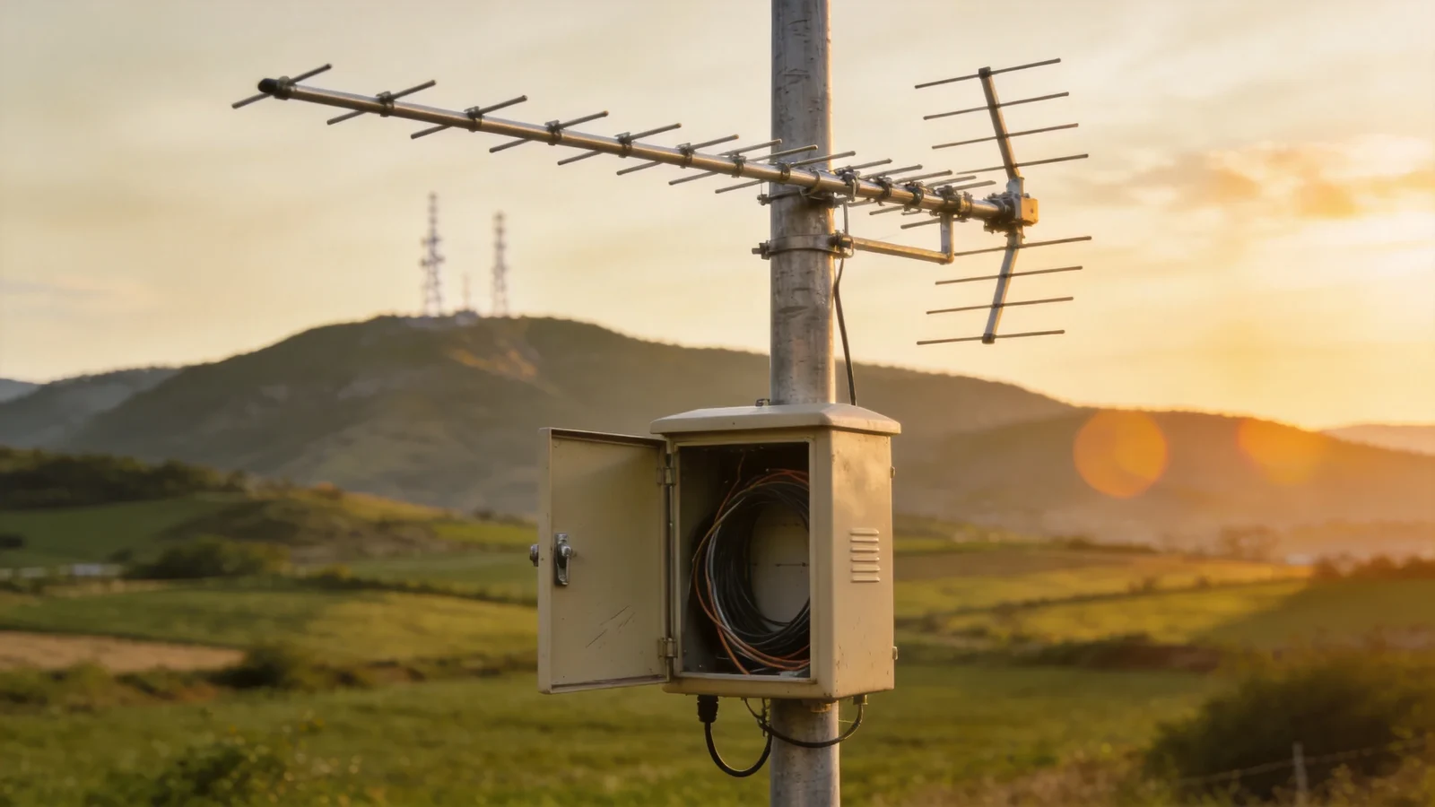
- Industrial telemetry and SCADA — 433/450/868/915 MHz links from remote sensors, meters, and pump stations back to a collection point. Our 433 MHz and 868 MHz Yagi models are built for exactly this class of link.
- Land mobile radio (LMR) base stations — VHF/UHF Yagis pointed at a repeater to serve a valley, a mine, or a highway corridor.
- Cellular signal improvement in fringe areas — a Yagi aimed at the nearest tower feeding a repeater or fixed router, common for rural sites and buildings.
- Point-to-point WiFi and ISM links — 2.4 GHz Yagis bridging buildings or connecting a remote camera. (For multi-band or MIMO bridges, panel antennas usually fit better — see the comparison links below.)
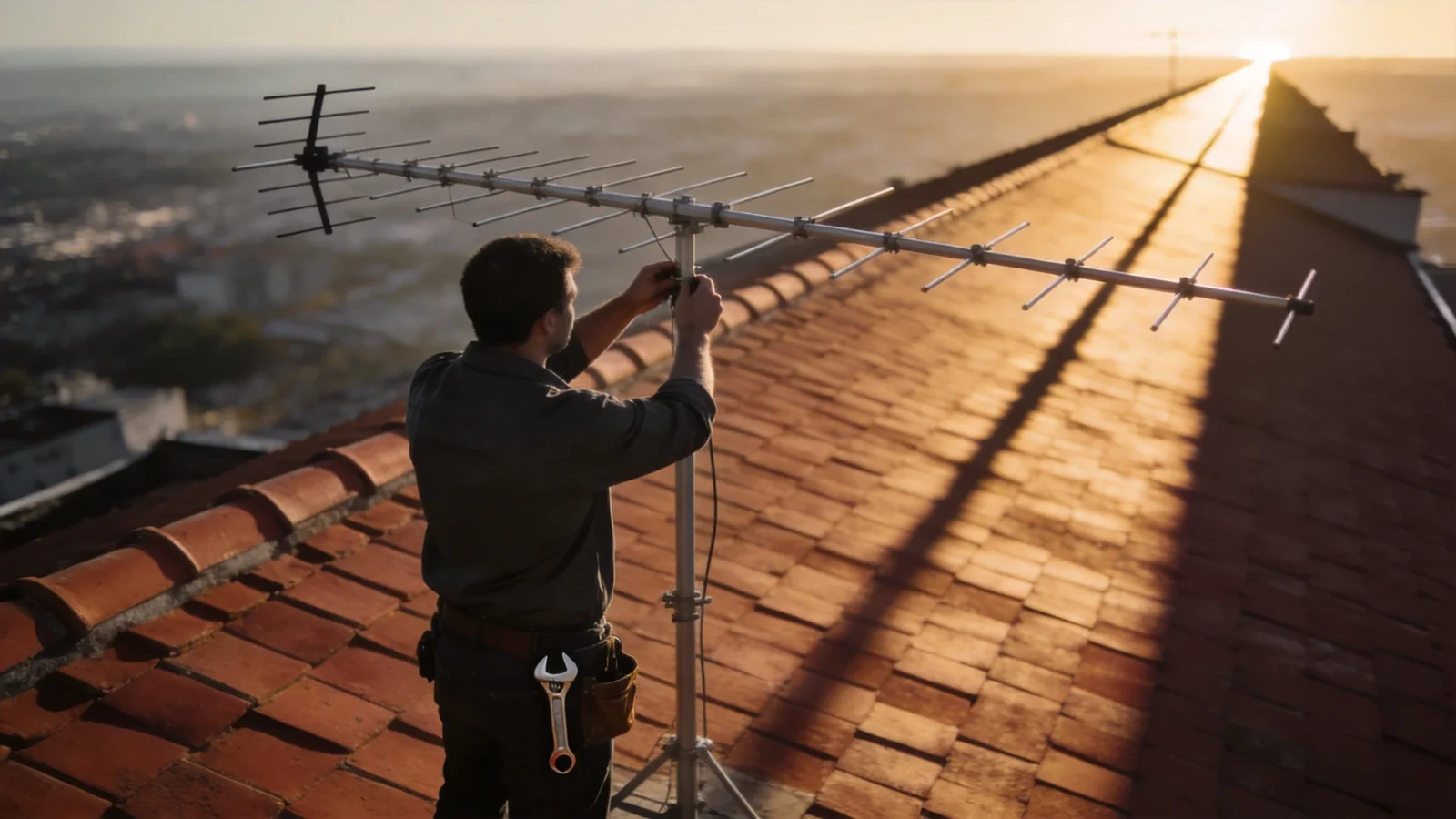
- TV reception — the classic rooftop application and still the most visible Yagi in the world.
- Amateur radio and DXing — rotatable HF/VHF Yagis remain the standard tool for working distant stations.
- Wildlife tracking and direction finding — handheld Yagis locate radio-tagged animals and interference sources, exploiting the sharp pattern rather than the gain.
The common thread: both ends of the link stay put, or the operator can aim. If the device moves — vehicles, handhelds, roaming nodes — an omnidirectional antenna is the right call, and a Yagi is the wrong one.
Yagi vs other directional antennas
Short version: against an LPDA, the Yagi wins on gain per dollar at a single band, the LPDA wins on bandwidth; against a panel antenna, the Yagi offers a longer, narrower reach while the panel gives a cleaner sector shape, easier MIMO pairing, and lower visual profile. We keep full comparisons with radiation-pattern plots in Yagi vs LPDA Antenna and Panel Antenna vs Yagi Antenna rather than repeating them here. If you are new to log-periodic designs, start with our guide to log-periodic dipole array (LPDA) antennas.
How to choose a Yagi antenna
- Frequency first. The antenna must cover your exact operating range — a 450–470 MHz Yagi is not a 433 MHz Yagi. Bandwidth is narrow by design.
- Work out required gain from the link, not the catalog. Estimate path loss, subtract radio power and receiver sensitivity, and buy only the gain you need — every extra dB narrows the beam and lengthens the boom.
- Check beamwidth against your mounting reality. A 30° beam on a mast that sways in wind can point off-target. If precise alignment is impractical, trade gain for beamwidth.
- Match polarization to the far end. Most fixed links run vertical; cross-polarization silently costs more than any spec difference between two antennas.
- Look at F/B ratio when interference sits behind you — co-channel repeaters, a second site, urban noise.
- Verify mechanics. Boom length, wind survival rating, bracket type, and connector (N-type outdoors as a rule). A corroded cheap Yagi is a recurring maintenance ticket, not a bargain.
- Mind the ground plane myth. Yagis are complete antennas and need no ground plane — but they do need clearance: keep the boom a wavelength away from metal masts and walls where possible.
Looking for Yagi antenna products? Compare VHF, UHF, 433 MHz, 820-890 MHz and 2.4 GHz models on our Yagi antennas category page.
FAQ
What is a Yagi antenna used for?
Fixed, directional radio links: telemetry and SCADA backhaul, LMR base stations, rural cellular improvement, point-to-point WiFi, TV reception, ham radio, and radio direction finding. It suits any link where both ends stay put and extra gain or interference rejection is needed.
How does a Yagi antenna work?
Only the driven element is fed. The reflector and directors are passive rods whose induced currents re-radiate with phases that cancel the signal backward and reinforce it forward, concentrating energy into a single beam.
Is a Yagi antenna directional, and how far can it reach?
Yes — that is its defining feature. Range depends on frequency, gain, height, and terrain: multi-kilometre UHF telemetry links are routine with 10–12 dBi Yagis and clear line of sight, and longer paths are achievable with height and careful link budgeting.
What is the difference between a Yagi and an LPDA?
A Yagi puts all its elements to work at one band for maximum gain per length; an LPDA spreads its elements across a wide frequency range, trading gain for bandwidth. Details and pattern plots: Yagi vs LPDA.
What frequencies do Yagi antennas work on?
The design scales across roughly 30 MHz to 2.4+ GHz — element lengths scale with wavelength. Commercial models are built per band: VHF (150 MHz), UHF (400–470 MHz), ISM (433/868/900 MHz), and 2.4 GHz among the most common.
Conclusion
A century after Uda and Yagi published the design, the recipe has not changed: one driven dipole, a few passive rods, and a beam you can point. Use a Yagi when the link is fixed and the direction is known. Size the gain from your link budget rather than the biggest number in the catalog, and check polarization before blaming the hardware. Browse our VHF/UHF and ISM-band Yagi antennas — 433 MHz, 450–470 MHz, and 868 MHz models — or ask our engineering team to size a Yagi for your link.
[CTA — Browse Yagi antennas / Request a link recommendation]
Related guide: For another directional antenna geometry, see normal-mode and axial-mode helical antennas.
Ready to specify a product?
Get product suggestions and quotation details for your application.
Tell us the frequency range, installation space and interference scenario. We can suggest suitable anti-jamming or specialty antenna options.
Ask our AI antenna assistant. Enter a keyword or question for a free answer based on this article, Global RF Tech content, and general antenna/RF knowledge.
Do not submit confidential or personal information. Privacy Policy




