
Patch antenna category guide
Patch Antennas for GPS, GNSS and Compact Wireless Devices
Use this pillar page to compare patch antenna types, selection factors, applications, and related Rftech product pages. It is built for engineers and sourcing teams who need a practical path from antenna concept to sample discussion.
Selection factors
Compare the real constraints
Frequency band, polarization, patch size, ground plane, and active/passive architecture decide whether a patch antenna fits the final device.
Application paths
Move from use case to product
Open the matching GPS/GNSS, RHCP, application, or manufacturer page instead of searching through unrelated products.
Engineering resources
Use the topic library
Design, gain, bandwidth, radiation pattern, and selection guides are grouped below for deeper technical review.
Choose the right path first
Reference product category pages put selection paths close to the top. This page follows the same engineering-first pattern: choose the requirement, then open the most relevant product, application, or RFQ page.
Product path
GPS / GNSS patch antennas
Compare ceramic patch options for embedded positioning receivers, trackers, timing hardware, and GNSS modules.
Technical path
RHCP patch antenna selection
Review polarization, axial ratio, multipath rejection, and phase-center considerations for GNSS reception.
Application path
Patch antenna applications
Map use cases across asset tracking, telematics, RTK receivers, timing, and compact modules.
Commercial path
Manufacturer and OEM support
Prepare custom size, cable, connector, housing, documentation, and sample requirements for sourcing.
What is a patch antenna?
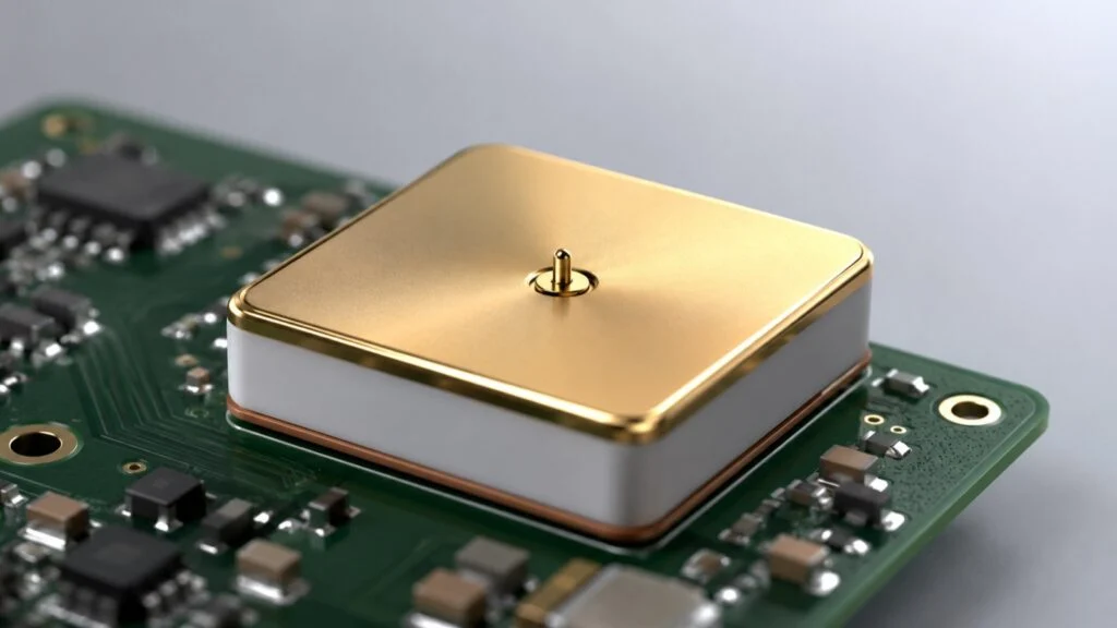
A patch antenna — also called a microstrip antenna — is a low-profile antenna built around a radiating patch, dielectric material, and ground plane. The resonant patch length is roughly half a wavelength inside the dielectric, so a substrate with a higher dielectric constant makes the patch physically smaller. That is why ceramic patch antennas dominate GPS and GNSS devices: high-dielectric ceramic shrinks the element enough to fit compact hardware while keeping the right-hand circular polarization that satellite signals require.
For product selection, the useful decision is whether the size, frequency band, polarization, gain, axial ratio, ground plane, cable, connector, and active or passive architecture match the final device.
Best starting point
If your requirement is GPS or GNSS positioning, start with the GPS patch antenna page. If your main concern is polarization quality, continue to the RHCP patch antenna technical page.
Main patch antenna types
| Type | Best for | Selection notes | Related page |
|---|---|---|---|
| Passive ceramic patch | Short RF paths and receiver boards | Check size, ground plane, band, polarization, impedance, and enclosure placement. | GPS patch antennas |
| Active GPS/GNSS patch assembly | Longer cable runs or remote mounting | Confirm LNA gain, bias voltage, noise figure, cable loss, connector, and filtering needs. | Manufacturer support |
| RHCP patch antenna | GNSS reception where circular polarization matters | Review axial ratio, phase-center stability, ground plane, and mounting position. | RHCP selection |
| Multi-band GNSS patch | Receivers using L1 plus additional GNSS bands | Check datasheet band coverage, dimensions, mechanical stack, and receiver compatibility. | Compare products |
| Custom cable or housing assembly | Projects that need a finished antenna | Prepare cable length, connector, mounting, label, packing, and compliance requirements. | OEM RFQ |
| GPS puck antenna | Vehicle roofs, asset trackers, metal surfaces | A ceramic patch sealed in a low-profile housing; check mounting type (magnetic, screw, adhesive), cable length and connector. | Puck antennas below |
GPS puck antennas: patch antennas in a housing
A puck antenna is not a different antenna technology — it is a ceramic GPS/GNSS patch antenna sealed inside a low-profile weatherproof housing, usually 40-50 mm across and under 20 mm tall, with a magnetic base, screw stud or adhesive pad and a pre-terminated cable. The name comes from the hockey-puck shape. Inside, the same rules from this page apply: RHCP reception on 1575.42 MHz GPS L1 and 1601-1610 MHz GLONASS, with an LNA in active versions to cover the cable run.
| Model | Bands | Size | Mounting | Connector |
|---|---|---|---|---|
| GL-DY001 | GPS L1 + GLONASS | 49.4×39.3×14.9 mm | Magnet or adhesive | Fakra C |
| GL-DY002 | GPS L1 + GLONASS | 45.2×35.8×15.1 mm | Magnetic | SMA plug / MCX |
| GL-DY003 | GPS L1 + GLONASS | Φ46.6×14.5 mm disc | Screw mount | Fakra C / SMA |
| GL-DY008 | GPS L1 + GLONASS | 50×37×17 mm | Magnetic | SMA male |
Choosing between the two: embed a bare ceramic patch when the antenna lives inside your product and you control the ground plane; specify a GPS puck when the antenna sits outside — on a vehicle roof, a container, a metal cabinet — and needs sealing and a mount. Fleet and telematics installers typically order GPS pucks pre-terminated with the exact cable and connector, which is how we supply them: pick a model above, or send your cable spec for an OEM build.
GNSS integration
Need help choosing a GNSS or patch antenna?
Tell us your device size, ground plane, constellation, cable and mounting requirements. We can help match active, passive or embedded GNSS antenna options.
Key specifications to compare
| Specification | Why it matters | What to prepare before RFQ |
|---|---|---|
| Frequency band | The antenna must match the receiver and GNSS band plan. | GPS, GLONASS, Galileo, BeiDou, L1/L2/L5 or other target bands. |
| Polarization | GNSS receivers usually need RHCP reception for satellite signals. | Confirm RHCP requirement and any axial-ratio target from the receiver design. |
| Patch size | Larger patches can provide more aperture, while smaller patches need tighter integration care. | Maximum length, width, height, and available ground-plane area. |
| Active or passive | Passive patches depend on receiver front-end placement; active assemblies compensate cable loss. | Bias voltage, LNA gain range, cable length, connector, and filtering needs. |
| Mounting environment | Nearby batteries, displays, metal parts, and enclosure material can change antenna margin. | Photos, mechanical drawing, PCB layout context, and mounting position. |
Typical ceramic patch antenna values
Use these typical figures as a sanity check when you compare ceramic patch antenna datasheets. Civil GNSS band frequencies follow the published signal plans (see the official GPS.gov civil signal specifications).
| Parameter | Typical value for ceramic GNSS patches | Notes |
|---|---|---|
| Center frequency | GPS L1 / Galileo E1 1575.42 MHz; GLONASS L1 ~1602 MHz; BeiDou B1I 1561.098 MHz; GPS L5 1176.45 MHz | Multi-band patches cover the 1559–1610 MHz upper L-band plus L5/B2a where specified. |
| Common patch sizes | 25 × 25, 18 × 18, 15 × 15, 12 × 12 mm | Smaller patches trade gain and bandwidth for board space and need tighter tuning to the ground plane. |
| Zenith gain (passive) | about 2–5 dBic on a 70 × 70 mm ground plane | Quoted gain depends on the test ground plane; a smaller plane in the real device lowers it. |
| Axial ratio | ≤ 3 dB at zenith | Lower is better for RHCP reception and multipath rejection. |
| VSWR / impedance | VSWR ≤ 2.0 in band, 50 Ω feed | Verify after mounting in the enclosure, not only on the evaluation jig. |
| Substrate dielectric constant | roughly 20–90 (ceramic) | Higher dielectric constant gives a smaller patch but narrower bandwidth and tighter detuning sensitivity. |
Common patch antenna applications
Location devices
Asset tracking
Compact tracking hardware needs a patch antenna that balances size, ground plane, receiver sensitivity, battery layout, and enclosure material.
Connected mobility
Vehicle telematics
Telematics terminals often combine GNSS with cellular, WiFi, or IoT radios, so antenna placement and cable routing matter.
Precision positioning
RTK and surveying receivers
Higher-accuracy receivers may require tighter attention to polarization, multipath behavior, phase-center stability, and band support.
Field equipment
Precision agriculture devices
Outdoor positioning hardware needs stable mounting, environmental protection, and a practical match between module and antenna assembly.
Infrastructure
Timing and synchronization
Timing receivers need consistent GNSS reception, clean cable routing, and suitable active antenna gain when mounted away from the receiver.
Embedded modules
Compact GNSS modules
Small modules need careful patch size selection, ground plane planning, and enclosure testing before production sampling.
Engineering guide library
Use these supporting guides when you need deeper context before choosing a product or sending an RFQ.
Engineering guide
Design guide
Layers, substrate, ground plane, and integration basics.
Engineering guide
Gain
How patch size, placement, and ground plane affect signal margin.
Engineering guide
Bandwidth
Bandwidth factors and when multi-band designs matter.
Engineering guide
How to choose
A practical checklist for engineering and sourcing teams.
Engineering guide
RHCP vs LHCP
Polarization choice for GNSS and circularly polarized systems.
Engineering guide
Advantages and limits
Where patch antennas fit well and where care is needed.
Engineering guide
Radiation pattern
Broadside pattern, beamwidth, and installation effects.
Engineering guide
Patch antenna basics
Plain-English introduction to microstrip and ceramic patch designs.
FAQ
FAQ
Is a patch antenna the same as a GPS antenna?
No. A GPS antenna can use different structures. A GPS patch antenna is a low-profile patch design tuned for GPS or GNSS reception.
FAQ
Should I choose active or passive?
Choose passive when the receiver front end is close and designed for it. Choose active when cable loss or remote mounting requires LNA support.
FAQ
Why do GNSS patches use RHCP?
GNSS satellite signals are circularly polarized, so RHCP patch antennas help receive the intended signal orientation and reduce some reflected-signal problems.
FAQ
What should I send before RFQ?
Send the receiver model, target bands, size limit, ground-plane area, active or passive need, cable, connector, enclosure, mounting position, and sample quantity.
FAQ
Is a microstrip antenna the same as a patch antenna?
In most product contexts, yes. Microstrip antenna is the textbook name for the same patch-on-dielectric structure. The ceramic patch antennas used in GNSS devices are a high-dielectric variant of the microstrip design.
FAQ
What is a GPS puck antenna?
A GPS puck is a ceramic patch antenna sealed in a small hockey-puck housing with a magnetic, screw or adhesive mount and a fixed cable — the standard external antenna for vehicle tracking and asset telematics.
FAQ
Puck antenna vs patch antenna — what is the difference?
The radiating element is the same. A patch antenna is the bare element for integration inside a device; a puck antenna is that element packaged with a housing, mount and cable for external installation. Choose by where the antenna will live, not by performance.
Need a patch antenna shortlist?
Send your module, frequency band, size limit, connector, cable length, mounting position, and expected quantity. Rftech can help narrow the product path before sampling.
Related GPS/GNSS Models for Selection
For GNSS patch and active antenna sourcing, compare the GL-DYS2502 1580 ±3 MHz GPS/GNSS ceramic antenna, GL-DY006 GPS/GNSS antenna with MCX right-angle connector, GL-DY006F Fakra C GPS/GNSS antenna, and GL-DY008L 1568 ±3 MHz GPS/GNSS antenna before requesting samples. For integration decisions, use our antenna connector types guide, ceramic antenna guide, and antenna polarization guide.
