MCX to RG174 Cable Assembly with Bare Copper End | GL8103P5
SKUGL8103P5
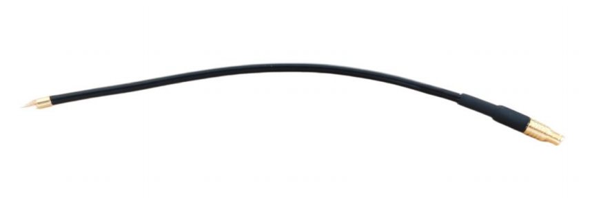
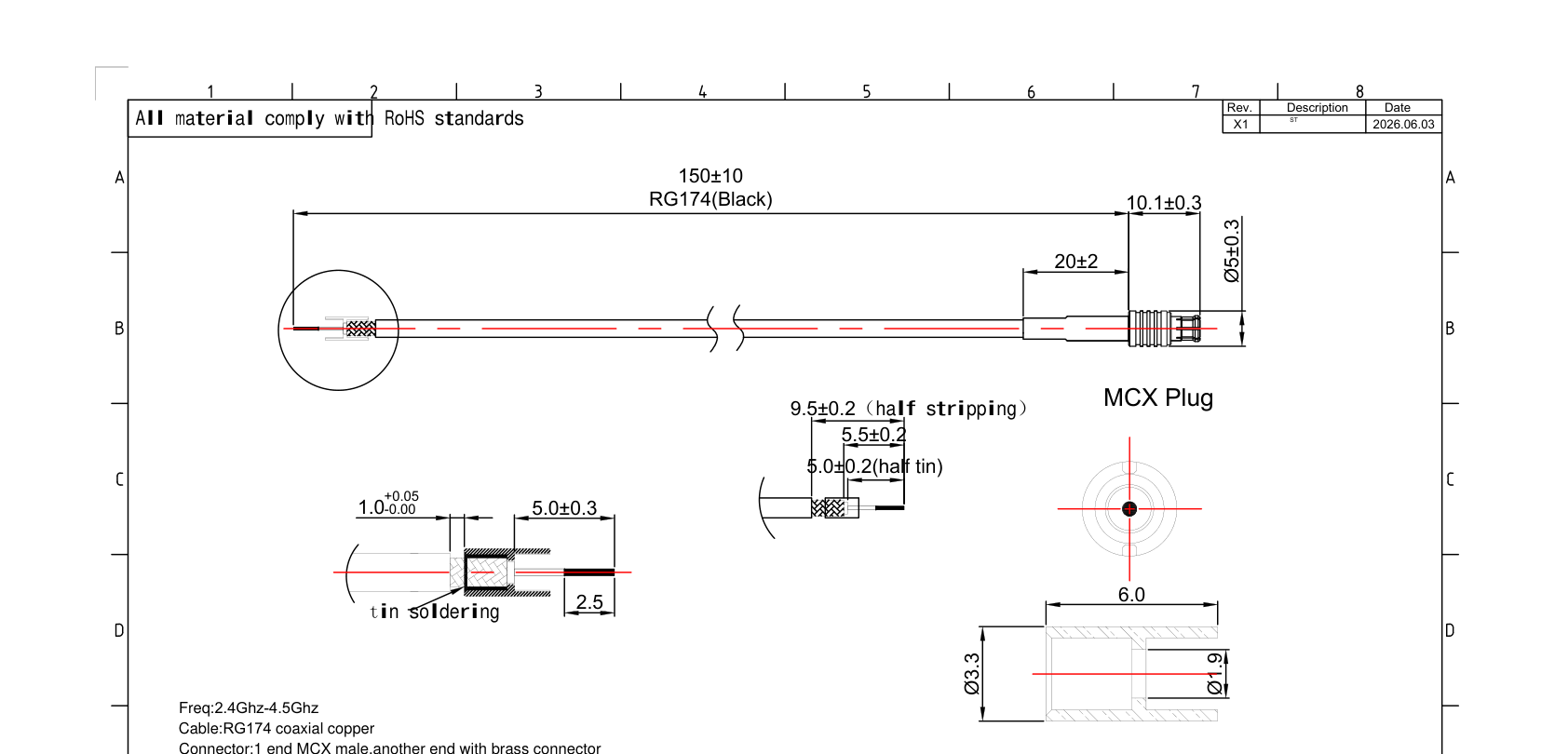
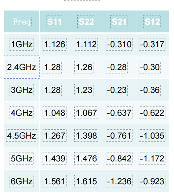
GL8103P5 is an MCX-to-RG174 coaxial cable assembly with a gold-plated MCX male connector and a bare copper soldering end. It uses 150 ± 10 mm black RG174 cable and is specified for 2.4–4.5 GHz, 50 Ohm impedance and VSWR below 2.0.
How this model fits the documented RF, interface and installation requirements.
Termination choice
A cable assembly defined by its bare soldering end
GL8103P5 is defined by its two different end terminations. One end has a gold-plated MCX male connector; the other is a bare copper soldering end with no PCB or inductor. This is the first distinction to check when comparing it with other MCX-to-RG174 assemblies.
The black RG174 coaxial cable has a specified end-to-end length of 150 ± 10 mm and includes a black 6.0 × 20 mm heat-shrink tube. Electrical limits are 2.4–4.5 GHz, 50 Ohm impedance and VSWR below 2.0.
The documented storage temperature is -20 to +65°C. Confirm that the bare end matches the intended soldering process and that the stated length tolerance fits the routing space.
TerminationMCX male to bare copper soldering end
Cable route150 ± 10 mm black RG174
Electrical range2.4–4.5 GHz · 50 Ohm · VSWR < 2.0
Current documentation
Downloads
Files shown here are linked to this exact product record.
Send the required band, connector, installation limits and quantity. We will review the request against the selected model.Request a Quote→
Compare product configurations
Compare the exact model and its published specifications before requesting a sample or production quote. A connector or cable change must be confirmed for the selected model.
Values below are copied from the individual product records. Where a unit or value is not stated, consult the model datasheet before specifying the part.
Before ordering
Match every required operating band, rather than relying only on a product-family name.
Check connector gender, cable route, mounting space and the interface on your device.
Use the exact model datasheet to confirm the test conditions and installation limits.
Select a standard model or discuss a change
For a standard configuration, send the model number and expected quantity. For a change, include the required band, enclosure space, cable length and connector. Sample availability, minimum order quantity and delivery are confirmed with the quotation.
Which specifications should I confirm for this model?
Use the listed frequency, connector and mounting information together. Compare the values with your radio interface and available installation space; do not substitute parameters from a similar-looking model.
Can I change the cable or connector?
Describe the cable length, connector type and installation constraints in your enquiry. A change is subject to review for this exact model; the published configuration is the reference until a revised specification is confirmed.
What should I send for a sample or production quote?
Include the model, expected quantity, delivery destination and any drawing or interface requirement. Ask for confirmation of the sample configuration, lead time and production terms before placing an order.
Discuss your antenna requirements
Send the model, operating band and installation requirements. We will review the configuration and confirm pricing, samples and delivery for your project.