Inner conductorSilver plated copper, 0.53 +/- 0.01 mm
DielectricPTFE (Solid), 1.68 +/- 0.05 mm
Outer conductorTin-plated copper wire braid (16*5*0.10), 2.17 +/- 0.05 mm
JacketFEP, Blue, 2.65 +/- 0.05 mm
Capacitance98 pF/m
Impedance50 +/- 2 ohm
Velocity70 %
Cutoff frequency60 GHz
Time delay4.7 ns/m
Min. bending radius static6 mm
Min. bending radius repeated2 mm
Operating temperature-65 to +150 deg C
Weight19 kg/km
Attenuation @ 0.5 GHz / Power0.49 dB/m / 338 W
Attenuation @ 1 GHz / Power0.72 dB/m / 219 W
Attenuation @ 2 GHz / Power1.07 dB/m / 142 W
Attenuation @ 3 GHz / Power1.34 dB/m / 110 W
Attenuation @ 5 GHz / Power1.80 dB/m / 80 W
Attenuation @ 10 GHz / Power2.67 dB/m / 52 W
Attenuation @ 18 GHz / Power3.73 dB/m / 36 W
CategoryCoaxial Cables & Connectors
Engineering selection guide
Product details
How this model fits the documented RF, interface and installation requirements.
RG405-50 cable selection
Compare the construction and stated loss table
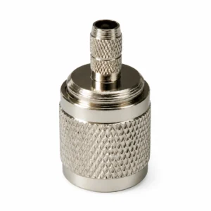
GLRG40550 is an RG405-50 coaxial cable with a silver-plated copper inner conductor, solid PTFE dielectric, tin-plated copper wire braid and blue FEP jacket. The datasheet lists 50 ±2 Ω impedance.
Its attenuation and power table is stated at 20 °C and sea level, with entries from 0.5 to 18 GHz. Compare the row for the intended frequency against the project loss budget and check the 2.65 ±0.05 mm jacket diameter and bending-radius entries against the cable route.
The datasheet lists 60 GHz as a cutoff frequency, not a verified operating band.
Send the required band, connector, installation limits and quantity. We will review the request against the selected model.Request a Quote→
Compare product configurations
Compare the exact model and its published specifications before requesting a sample or production quote. A connector or cable change must be confirmed for the selected model.
Values below are copied from the individual product records. Where a unit or value is not stated, consult the model datasheet before specifying the part.
Before ordering
Match every required operating band, rather than relying only on a product-family name.
Check connector gender, cable route, mounting space and the interface on your device.
Use the exact model datasheet to confirm the test conditions and installation limits.
Select a standard model or discuss a change
For a standard configuration, send the model number and expected quantity. For a change, include the required band, enclosure space, cable length and connector. Sample availability, minimum order quantity and delivery are confirmed with the quotation.
Which specifications should I confirm for this model?
Use the listed frequency, connector and mounting information together. Compare the values with your radio interface and available installation space; do not substitute parameters from a similar-looking model.
Can I change the cable or connector?
Describe the cable length, connector type and installation constraints in your enquiry. A change is subject to review for this exact model; the published configuration is the reference until a revised specification is confirmed.
What should I send for a sample or production quote?
Include the model, expected quantity, delivery destination and any drawing or interface requirement. Ask for confirmation of the sample configuration, lead time and production terms before placing an order.
Discuss your antenna requirements
Send the model, operating band and installation requirements. We will review the configuration and confirm pricing, samples and delivery for your project.