

MIMO and beamforming in 5G solve two different problems, and mixing them up is the most expensive mistake we see on antenna specifications. MIMO adds capacity by running several data streams over the same channel. Beamforming adds reach by pointing energy at the user instead of everywhere.
Short answer. Match the MIMO tier to what the modem can actually use — a 4×4 antenna on a 2×2 modem gains nothing. Use cross-polarized elements, and give every RF chain its own cable from element to modem port. Add beamforming, meaning a larger active array, when you need range or interference control rather than raw throughput. Most industrial and enterprise projects land on 4×4 or 8×8 with SMA or N-Type connectors; massive MIMO belongs to macro sites and ultra-dense venues.
We have specified and supplied MIMO antenna assemblies since the LTE era, for projects ranging from private 5G campuses to urban macro sites. This guide follows the order our engineers use in a pre-sales review: how many streams the system can really carry, what the band and array size do to coverage, which connector and polarization choices quietly cancel your MIMO gain, and where public standards give you a hard number instead of a marketing claim.
What Is MIMO in 5G Antennas?
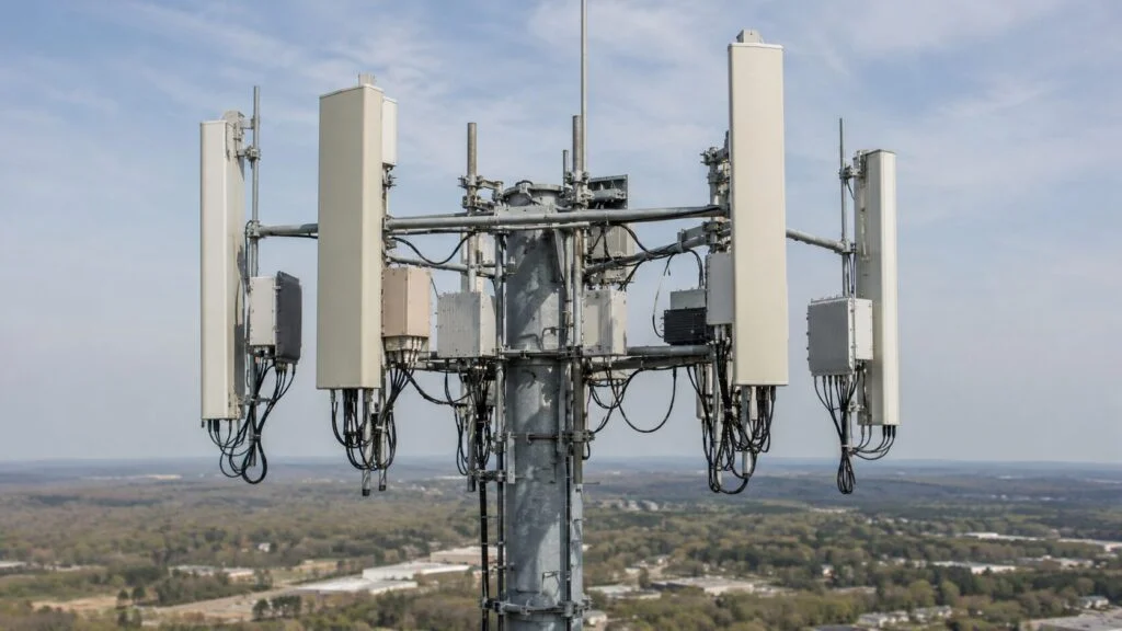
MIMO stands for Multiple-Input Multiple-Output. In antenna terms, it means the system uses multiple independent RF paths—each with its own antenna element, cable, and modem port—to transmit and receive data simultaneously over the same radio channel.
In 4G LTE, 2×2 MIMO was the baseline. In 5G NR, the industry has shifted upward. A typical enterprise-grade CPE now expects a 4×4 MIMO antenna 5G configuration. Macro base stations commonly deploy 64T64R massive MIMO arrays. The number in the MIMO label—4×4, 8×8, 64×64—describes the count of transmit and receive chains, not the number of visible antenna elements.
A 4×4 MIMO antenna 5G assembly contains at least four radiating elements, each fed by an independent RF cable. When the channel conditions support it—meaning sufficient multipath reflection and low correlation between paths—the modem can layer four independent data streams. The theoretical spectral efficiency gain is 4x. Across our own projects we typically see 2.5x to 3.5x over a comparable single-input system, which is still a substantial improvement. That range is our field experience, not a published measurement.
Why a 4×4 assembly cannot reach the headline 5G number
The 30 bit/s/Hz figure quoted for 5G comes with a condition almost nobody repeats. The ITU-R minimum technical performance requirements for IMT-2020 set downlink peak spectral efficiency at 30 bit/s/Hz and uplink at 15 bit/s/Hz, and those values were defined assuming an antenna configuration that enables eight spatial layers in the downlink and four in the uplink (ITU-R, IMT-2020 requirements). ETSI’s evaluation documents use the same arithmetic: four-layer spatial multiplexing corresponds to 16.0 b/s/Hz, and it takes eight layers to reach 30.0 b/s/Hz (ETSI TR 136 912).
So a 4×4 terminal, even with a perfect channel, works against half the layer count that the headline number assumes. That is the honest ceiling to write into an acceptance document.
The one formula worth keeping in your spec file
3GPP’s terminal data-rate calculation (ETSI TS 138 306, clause 4.1.2) multiplies the number of layers, the modulation order, a maximum code rate of 948/1024, a scaling factor, the bandwidth and numerology, and an overhead term (ETSI TS 138 306). Two things fall out of it:
- Layers scale the rate linearly. Moving from 256QAM to 1024QAM adds only about 25 percent in nominal terms, and needs a very high signal quality to hold.
- The scaling factor can legally be 1, 0.8, 0.75 or 0.4. Two devices both labelled 4×4 can therefore differ by more than a factor of two in supported rate. Ask for the reported value, not the label.
Both are engineering estimates you can run yourself, not measured results.
2×2 vs 4×4 vs Massive MIMO: How to Choose
The correct MIMO tier depends on the device count, throughput target, and budget. Based on our project history across Asia-Pacific, European, and North American deployments, the following framework holds consistently:
| Configuration | Typical Use Case | Device Category | Complexity | Relative Antenna Cost |
|---|---|---|---|---|
| 2×2 MIMO | IoT gateways, cost-sensitive CPE, legacy upgrades | Fixed wireless terminals, industrial sensors | Low | Baseline |
| 4×4 MIMO | High-throughput enterprise CPE, premium small cells | Outdoor CPE, enterprise routers, private 5G base stations | Medium | +20–30% |
| 8×8 / 16×16 | Dense urban small cells, transport hubs, stadiums | Advanced small cell units, sector arrays | High | +50–70% |
| 64T64R Massive MIMO | Macro cells, urban capacity layers, mmWave gNB | Macro base stations, large venue systems | Very High | Significant |
4×4 MIMO antenna 5G configurations have become the practical standard for industrial and commercial projects. They deliver strong throughput gains without the cost and power penalties of massive arrays, and they are fully supported by Qualcomm X55/X62/X65 and MediaTek T800 modem platforms.
Massive MIMO is essential for macro-layer and high-density venues. If your project involves a stadium, airport terminal, or central business district macro site, massive MIMO is non-negotiable. For a standard industrial campus, manufacturing facility, or warehouse private network, 4×4 or 8×8 provides sufficient capacity at a fraction of the hardware cost.
Connector Standards for MIMO Antenna Arrays
MIMO performance depends on the entire RF chain, not just the antenna elements. The cable, connectors, and adapters between the antenna and the modem introduce loss and impedance mismatches that degrade the spatial independence MIMO requires.
For external MIMO antenna assemblies, we frequently see compatibility issues at the connector level. Many CPE devices ship with TS-9 ports for compactness, but third-party antennas use SMA or N-Type connectors. A TS-9 to SMA 5G external MIMO antenna adapter cable is then required to bridge the two standards.
| Connector | Typical Use Case | Insertion Loss at 3.5 GHz | Durability |
|---|---|---|---|
| TS-9 | Consumer CPE, portable hotspots | Moderate | Fragile; not rated for high mate/demate cycles |
| SMA | Enterprise CPE, external antennas | Low | Good; standard for outdoor assemblies |
| RP-SMA | Wi-Fi and consumer 4G/5G equipment | Low | Good; reverse polarity for regulatory compliance |
| N-Type | Macro cells, tower-mounted antennas | Very low | Excellent; standard for infrastructure |
Our recommendation for project deployments: specify antennas with SMA or N-Type connectors whenever possible. If the CPE device requires TS-9, use a short, high-quality adapter and account for the 0.5 to 1.0 dB insertion loss in the link budget. Never run a 4×4 MIMO array through splitters or shared coaxial paths; each RF chain must remain independent from antenna element to modem port.
What Is Beamforming and How It Works
Beamforming is the active steering of radio energy toward specific receivers rather than broadcasting uniformly. In 5G, beamforming is implemented through phased arrays: a cluster of antenna elements where the signal phase at each element is adjusted to constructively interfere in the target direction and destructively interfere elsewhere. Concentrating the signal in one direction raises its chance of arriving intact and lowers interference for everyone else (IEEE Spectrum).
There are two primary architectures:
- Analog beamforming: Uses analog phase shifters to create a single beam direction. It is fast, power-efficient, and cost-effective, but limited to one beam at a time per RF chain.
- Digital beamforming: Each antenna element (or sub-array) has an independent RF chain and digital baseband path. This enables multiple simultaneous beams, user-specific tracking, and advanced multi-user MIMO (MU-MIMO).
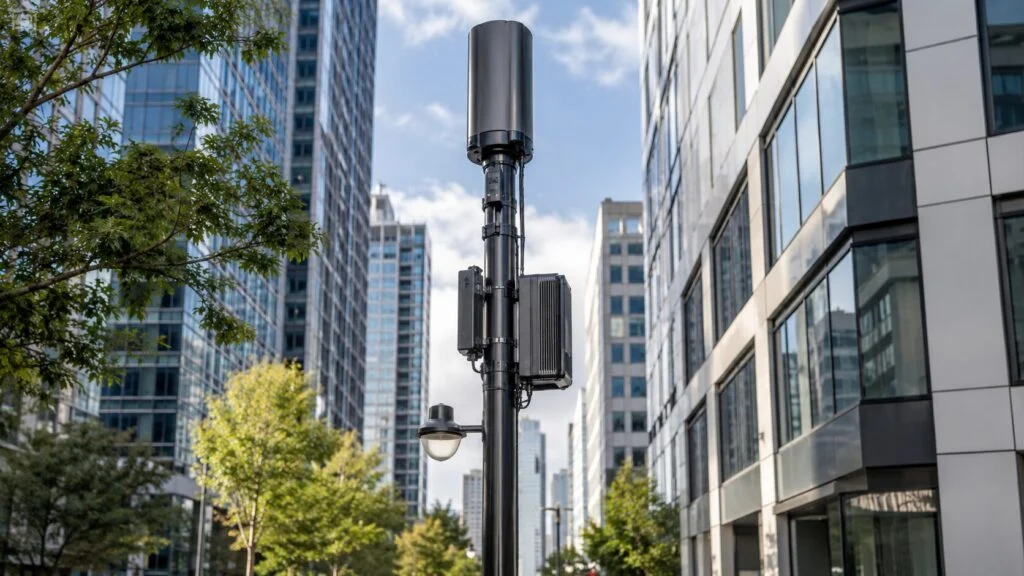
A 5G beamforming antenna for macro deployment typically contains 64 to 256 radiating elements in a planar array, controlled by a baseband unit that shapes and steers beams in real time. Beamwidths as narrow as 3 to 10 degrees are common at mmWave frequencies. At sub-6 GHz, beamwidths are wider—typically 15 to 30 degrees—but the principle remains the same.
For scale: 4G LTE antennas use only two to four elements per antenna, while massive MIMO arrays use hundreds and add nullforming to cancel interference between users (NIST).
The coverage math you can run yourself
Free-space loss follows a formula published by the ITU:
FSPL (dB) = 20 x log10(d_km) + 20 x log10(f_GHz) + 92.45Both variables sit inside a 20-log term, so two rules of thumb follow: double the distance, add 6 dB; double the frequency, add 6 dB (ITU-R P.525-4).
The antenna side has a matching limit. Element spacing is roughly half a wavelength, so doubling the frequency halves that spacing and lets about four times as many elements fit the same panel area, worth roughly 6 dB of extra aperture gain. At a fixed panel size, the added path loss and the added array gain roughly cancel.
That is why a 3.5 GHz array can come close to low-band coverage, and why mmWave cannot be fixed the same way: 28 GHz sits 20 x log10(28 / 3.5) ≈ 18 dB further back. No fixed-size panel closes an 18 dB gap. Shorter links, a physically larger aperture or tighter site spacing do. Treat these as engineering estimates rather than measured link budgets.

Narrow beams do not help your control channels
User-specific narrow beams carry data. Broadcast and control signalling still has to cover the whole cell, so 5G NR sweeps synchronization signal blocks (SSB) across it, and that process is capped: SSB sweeping is limited to 4, 8 or 64 beams, each restricted to 240 subcarriers and 4 symbols, roughly 5 percent or less of downlink resources, while CSI-RS can span a whole bandwidth part with up to 32 ports (Dreifuerst and Heath, IEEE Communications Magazine).
Two consequences for specification work:
- A 64T64R gain figure describes data throughput. Cell-edge access, paging and control coverage do not improve in the same proportion.
- If the real complaint on site is that users cannot connect at the edge, a bigger array is the wrong purchase. Site placement, downtilt and a low-band layer will do more.

Where Beamforming Delivers Value in Commercial Projects
| Deployment Scenario | Beamforming Benefit | Recommended Array Size |
|---|---|---|
| Urban macro cell | Interference reduction, frequency reuse, capacity multiplication | 64T64R |
| Indoor DAS replacement | Precise zone coverage, wall penetration targeting | 16T16R to 32T32R |
| Fixed wireless access (FWA) | Stable CPE link, compensation for rain fade | 8×8 to 16×16 |
| Private 5G (factory / warehouse) | Device tracking, low-latency edge coverage | 4×4 to 8×8 |
| Stadium or convention venue | Parallel multi-user streams in ultra-dense environments | 64T64R |
In FWA deployments, beamforming is particularly valuable because it compensates for the limited transmit power of customer-premise equipment. By concentrating base station receive sensitivity in the direction of the CPE, beamforming extends coverage range without requiring more powerful—or more expensive—client-side hardware. That same antenna-side planning logic also shows up in premium small cells and indoor capacity overlays.
MIMO and Beamforming Selection Checklist
Before releasing a technical specification to procurement, confirm the following. These are the validation steps our engineering team applies to every custom antenna order:
- Modem MIMO tier alignment: Does the target device or baseband support 2×2, 4×4, or 8×8? A 4×4 MIMO antenna 5G assembly connected to a 2×2 modem yields no MIMO gain beyond the modem’s capability.
- Band and frequency plan: MIMO spatial multiplexing performs best in sub-6 GHz bands, where wavelengths still allow practical element spacing. Use the standard ranges when writing the spec: n77 covers 3300–4200 MHz, n78 covers 3300–3800 MHz and n79 covers 4400–5000 MHz, all TDD (3GPP). mmWave deployments lean on beamforming instead, for the path-loss reason shown above.
- Physical form factor constraint: A 64T64R massive MIMO 5G antenna panel is large, heavy, and wind-loaded. A 4×4 outdoor antenna is compact. Match the antenna size to the mounting structure and zoning requirements.
- Power budget for active arrays: Active beamforming arrays require DC power for RF chains and baseband processing. Passive MIMO antennas do not. Verify power availability at the mounting location.
- Channel environment assessment: Rich multipath environments—urban canyons, indoor reflective spaces—favor MIMO. Line-of-sight rural FWA links favor beamforming. Many real-world deployments benefit from both.
- Polarization requirement: Cross-polarized elements (+45° and -45°) are required for true MIMO performance; single-polarization arrays cannot reach rated spatial multiplexing capacity. What dual polarization really buys is size — a 3GPP working-group contribution noted that at 2 GHz, a four-antenna dual-polarized array needs only about 7.5 cm of linear space (3GPP R1-01-0406). The trade-off is that performance then depends on cross-polar discrimination (XPD) rather than element spacing, so ask for the XPD figure instead of accepting a dual-polarized label.
Common Specification Mistakes We See in the Field
Through technical support and return-material reviews, we have identified the following recurring errors in MIMO antenna specification:
- Overspecifying MIMO tier: Deploying massive MIMO for a 50-device private network wastes capital and power. Match the specification to the user density.
- Underspecifying for the environment: A single-element antenna in a convention center or stadium guarantees capacity collapse during peak load.
- Single-polarization MIMO claims: Some low-cost antennas advertise “MIMO support” but use single-polarization elements. Verify the datasheet specifies dual-slant or cross-polarized configuration.
- Cable sharing: Running four MIMO chains through a single coaxial cable with a splitter destroys the spatial independence that MIMO depends on. Each chain requires a dedicated cable from element to port.
- Ignoring connector loss at mmWave: At 28 GHz, even a short TS-9 adapter can introduce 2 to 3 dB of loss. For mmWave external antennas, integrated cable assemblies with direct PCB-to-antenna transitions are strongly preferred.
Summary
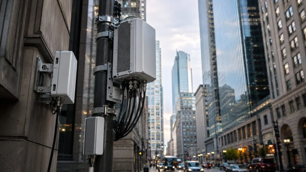
MIMO multiplies throughput by exploiting spatial diversity. Beamforming extends range and reduces interference by concentrating energy where it is needed. In 5G infrastructure, the two technologies work together: MIMO provides the capacity layer, and beamforming provides the coverage precision.
For most industrial and commercial projects, a 4×4 MIMO antenna 5G assembly with cross-polarized elements, SMA or N-Type connectivity, and IP65-rated outdoor housing is the practical baseline. Upgrade to massive MIMO only when user density or spectral efficiency targets justify the additional cost, power, and structural load. Always verify the full RF chain—from connector to modem port—before finalizing the specification, and check the modem’s reported layer count and scaling factor before promising a throughput number.
FAQ
What does MIMO mean in 5G antennas?
MIMO stands for Multiple-Input Multiple-Output. The system uses multiple independent RF paths, each with its own antenna element, cable, and modem port, to transmit and receive data simultaneously over the same radio channel.
How much throughput gain does 4×4 MIMO actually deliver?
The theoretical gain is 4x. Across our own projects we typically see 2.5x to 3.5x over a comparable single-input system, which is still a substantial improvement. Keep in mind that the IMT-2020 headline figure of 30 bit/s/Hz assumes eight downlink layers, so a 4×4 assembly sits structurally below it.
What is beamforming, and how does it differ from MIMO?
Beamforming actively steers radio energy toward specific receivers using phased arrays. In 5G the two work together: MIMO provides the capacity layer, while beamforming provides coverage precision and interference reduction.
What connector practice should MIMO antenna arrays follow?
Specify SMA or N-Type connectors where possible, keep each RF chain on its own dedicated cable rather than sharing through splitters, and account for roughly 0.5 to 1.0 dB of loss if a TS-9 adapter is required.
How many MIMO layers does 5G actually assume?
The IMT-2020 peak spectral efficiency figures, 30 bit/s/Hz downlink and 15 bit/s/Hz uplink, were defined assuming eight downlink layers and four uplink layers. A 4×4 assembly works with half that layer count, so quote its ceiling accordingly.
Does a bigger array always mean better coverage?
Not on every channel. Larger arrays improve user-specific data beams, but broadcast and control signalling relies on SSB sweeping with a hard cap on the number of beams, so cell-edge access does not improve in the same proportion.
Related Articles and Antenna Options
- Read more: 5G Small Cell and DAS antenna solutions
- Read more: 5G mmWave antenna deployment
- Read more: external MIMO antennas for LTE and 5G FWA routers
- Related product or next step: 4×4 outdoor MIMO antenna option
- Related product or next step: multi-band MIMO antenna for enterprise deployments
- Related product or next step: request a custom antenna quote
Ask our AI antenna assistant. Enter a keyword or question for a free answer based on this article, Global RF Tech content, and general antenna/RF knowledge.
Do not submit confidential or personal information. Privacy Policy




