

A 5G mmWave antenna is an active phased array with the radio built into it, and that single fact decides almost every planning question you will face: how far the cell reaches, how much power the site needs, and where the antenna can legally and physically go.
Short answer: Treat mmWave as a capacity overlay, never a coverage layer. Expect 100–300 m cells in dense urban areas, 20–30 dBi of array gain from 256–1,024 elements, 200–500 W per active site, and a mandatory sub-6 GHz layer underneath. In clear line of sight the link is rarely limited by path loss — it is limited by glass, foliage, vehicles and bodies.
The real question is not whether mmWave is fast. It is whether a specific link will close at a specific site. We have supplied sub-6 GHz and mmWave antenna assemblies for projects across North America, Europe, and East Asia, and this article walks through the judgement criteria we use in pre-deployment reviews: which 3GPP band you are buying hardware for, how the link budget actually adds up, what building materials really cost you, and where the regulatory EIRP ceiling sits. For the sub-6 anchor layer that usually sits underneath these projects, see our guide to 5G small cell and DAS antenna solutions.
What Is mmWave in 5G?
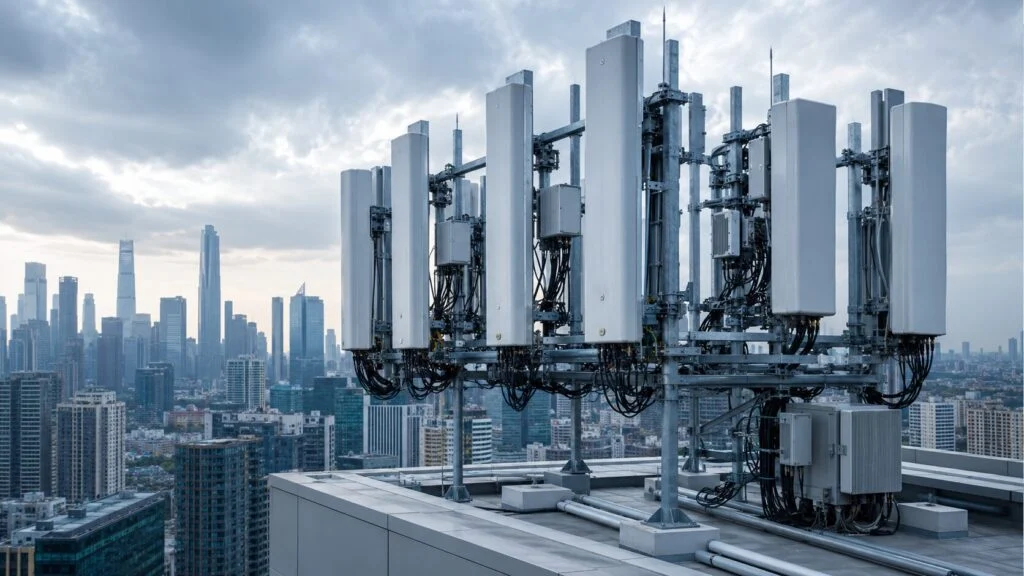
In 5G NR, “mmWave” is the informal name for Frequency Range 2 (FR2): 24.25 GHz to 71 GHz, where one carrier can be up to 400 MHz wide instead of the 100 MHz ceiling that applies in sub-6 GHz FR1. The operating bands are defined in 3GPP TS 38.101-2. These are the ones that matter when you select hardware:
| 3GPP Band | Frequency Range | Primary Region |
|---|---|---|
| n257 | 26.5 – 29.5 GHz | Japan, Korea, trial markets |
| n258 | 24.25 – 27.5 GHz | Europe, parts of Asia |
| n259 | 39.5 – 43.5 GHz | Global (later allocation) |
| n260 | 37 – 40 GHz | United States |
| n261 | 27.5 – 28.35 GHz | United States |
| n262 | 47.2 – 48.2 GHz | Global (early-stage allocation) |
| n263 | 57 – 71 GHz | United States (unlicensed-adjacent) |
These bands differ from sub-6 GHz 5G (n77, n78, n79) in three ways that directly affect antenna specification: propagation loss, atmospheric absorption, and building penetration.
One commercial reality belongs here too. mmWave is still a niche layer worldwide: as of July 2025 the GSA counted 203 operators in 56 countries and territories investing in 5G mmWave, but only 24 operators in 17 countries with a launched commercial mmWave network. For a project that means fewer band variants in volume production, longer lead times on n260 and n262 parts, and a real risk that the band you specify has no local device ecosystem to talk to.
Propagation Challenges at mmWave Frequencies
Free Space Path Loss Is Real, but It Is Not the Real Limit
Path loss rises with the square of frequency. Moving from 3.5 GHz to 28 GHz costs 20 × log₁₀(28 / 3.5) ≈ 18 dB at the same distance, before any obstacle is involved. You can check any case with the standard free-space formula:
FSPL (dB) = 32.44 + 20 × log₁₀(f in MHz) + 20 × log₁₀(d in km)
At 28 GHz that gives about 107 dB at 200 m and about 137 dB at 6.3 km. Read those two numbers together, because the conclusion is counter-intuitive: a 30 dB increase in loss buys a 30-fold increase in distance. A 200 m mmWave cell is nowhere near the edge of what physics allows, and operators running extended-range mmWave fixed wireless have closed links several kilometres long in clear line of sight.
So why are real cells 100 to 300 m wide? Blockage. A body, a delivery van, a leafy street tree or a coated window can remove 10 to 40 dB instantly, and no amount of array gain recovers a path that no longer exists. Free-space loss is a fixed cost you can budget once; blockage is a moving target that decides whether the site works at all. That is why beam management, site geometry and a fallback layer matter more than the last decibel of antenna gain.
A mmwave 5g antenna still has to pay the fixed cost, and deployments use three levers at once: array gain through beamforming, higher EIRP within regulatory limits, and a smaller cell radius that keeps most users in clear view of the antenna.

Rain and Atmosphere: Link Length Matters More Than Weather
Rain attenuation is a per-kilometre effect, so its impact depends almost entirely on how long the link is. The ITU model (ITU-R P.838) expresses it as specific attenuation:
γ = k × R\^α (dB/km), where R is the rain rate in mm/h
Interpolating the P.838 coefficients at 28 GHz for horizontal polarisation (roughly k ≈ 0.17, α ≈ 1.03) gives about 9–10 dB/km in heavy rain of 50 mm/h. Apply that to two different link lengths and the picture changes completely:
- 200 m urban small cell: roughly 2 dB of rain fade. Real, but smaller than the loss from one passing truck.
- 5 km FWA link: tens of dB. Here rain, not distance, sets your availability number.
These are engineering estimates from the ITU model rather than measurements at your site, but the ratio is the useful part: budget 2–3 dB for short cells, and treat rain as a first-order design driver only once links run past roughly a kilometre. Mobile users will still fall back to sub-6 GHz long before rain becomes their problem.
Oxygen behaves differently because it never stops. Near 60 GHz, oxygen absorption lines merge into one broad band worth roughly 10–16 dB/km at sea level (ITU-R P.676). For n263 (57–71 GHz) that rules out outdoor macro coverage, but it is better read as a feature than a defect: the atmosphere itself contains your signal, which makes dense frequency reuse and physically isolated links easy. It is why 60 GHz suits short indoor links and wireless backhaul.
Building Penetration: The Glass Decides Everything
mmWave does not pass through buildings in any useful way — high-band signals can lose over 100 dB crossing common construction materials. What surprises most planners is how much the type of glass matters. Measurements published through the Telecom Infra Project put usable numbers on it:
| Material | Loss at 28 GHz | What it means in practice |
|---|---|---|
| Single-pane clear glass | ~3 dB | Window-mounted CPE works well |
| Drywall | ~0.8 dB per layer | Interior partitions are survivable |
| Plywood | ~2.9 dB/cm | Temporary structures degrade the link |
| Tinted glass | ~13–19 dB | Marginal; CPE placement becomes critical |
| Low-E double glazing | ~30 dB | About 0.1% of the signal gets inside |

There is an awkward conclusion in that table. The energy-efficiency rules that made low-emissivity coated glass standard in new buildings across Europe, North America and China also made those buildings nearly opaque at 28 GHz. A brand-new office tower is often a worse mmWave environment than a 1970s building with plain single glazing. Survey the glazing before you promise anyone indoor coverage from an outdoor cell.
Two direct implications for antenna deployment:
- Outdoor mmWave cells serve outdoor users and indoor users near windows. Deep indoor coverage requires dedicated indoor mmWave cells or a sub-6 GHz DAS overlay.
- Window-mounted CPE is the standard FWA architecture. The customer antenna is placed on an exterior window facing the base station, with the router inside connected by short coax or Ethernet.
mmWave Antenna Architecture
A 5G mmWave antenna is not a passive radiator in the traditional sense. Because wavelengths at 28 GHz are approximately 10.7 mm, antenna elements are physically tiny. This allows hundreds of elements to be packed into a compact panel.
Phased Array Design
Typical mmWave base station antennas contain 256 to 1,024 individual radiating elements arranged in a planar array. Each element or sub-array has its own phase shifter, allowing the array to form narrow beams electronically without mechanical movement.
- Beamwidth: As narrow as 3° to 10°
- Beam steering range: ±60° horizontally, ±15° vertically (typical)
- Number of simultaneous beams: 8 to 64, depending on baseband capacity
- Array gain: 20 to 30 dBi
This beamforming gain is what makes mmWave coverage economically viable. A 256-element array with 25 dBi gain can close a 200-meter link at 28 GHz with reasonable transmit power levels that comply with regulatory EIRP limits.
mmWave Antenna Module Integration
A 5G mmWave antenna module typically integrates the phased array, RF transceivers, baseband processing, power supply, and thermal management in a single enclosure. Integration is not merely a packaging convenience; it is a technical necessity. The same array-planning mindset also shows up in MIMO and beamforming selection at lower frequencies.
Cable loss at 28 GHz is severe. Even a short coaxial cable between a remote RF unit and a passive antenna can introduce several dB of loss. By integrating the RF transceivers directly behind the antenna array, the design eliminates this loss entirely. The digital baseband signal is transported to the module over fiber or Ethernet, not analog RF.
Deployment Models for mmWave Antennas
Urban Dense Capacity (Street-Level)
In dense urban cores, mmWave small cells are mounted on street poles, building facades, and traffic lights at 6- to 10-meter heights. The coverage radius per cell is typically 100 to 300 meters.
Antenna requirements:
- Compact form factor for zoning compliance and concealment
- Wide azimuth scanning (±60° or more) to track moving devices
- High EIRP to overcome path loss
- Weather sealing for continuous outdoor exposure
Fixed Wireless Access (FWA)
FWA uses mmWave to deliver fiber-like speeds to homes and businesses without trenching fiber. The architecture is point-to-multipoint: a base station on a tower or building roof serves multiple CPE devices within a 500-meter radius. On the customer side, these projects often get evaluated alongside external MIMO antennas for LTE and 5G FWA routers.
Antenna requirements:
- High gain (25+ dBi) for maximum reach
- Narrow beams to maximise spectral efficiency per sector
- Mechanical and electrical tilt for rooftop-to-window alignment
- Rain fade margin sized to the actual link length
Indoor mmWave Coverage
Indoor mmWave is still an emerging deployment category. Primary use cases:
- Enterprise private networks: high-capacity indoor zones such as convention centres, smart factories and automated warehouses
- Venue densification: stadiums and arenas where sub-6 GHz spectrum is fully loaded
- Wireless backhaul: short-range, high-speed links between network nodes inside a building
Indoor mmwave antenna 5g units are compact modules, often ceiling-mounted, with integrated baseband. Because wall penetration is poor, the spatial density of indoor mmWave antennas is higher than for sub-6 GHz DAS. Expect one antenna per 100 to 200 square meters of coverage area.
The 5G Antenna Frequency Range Question
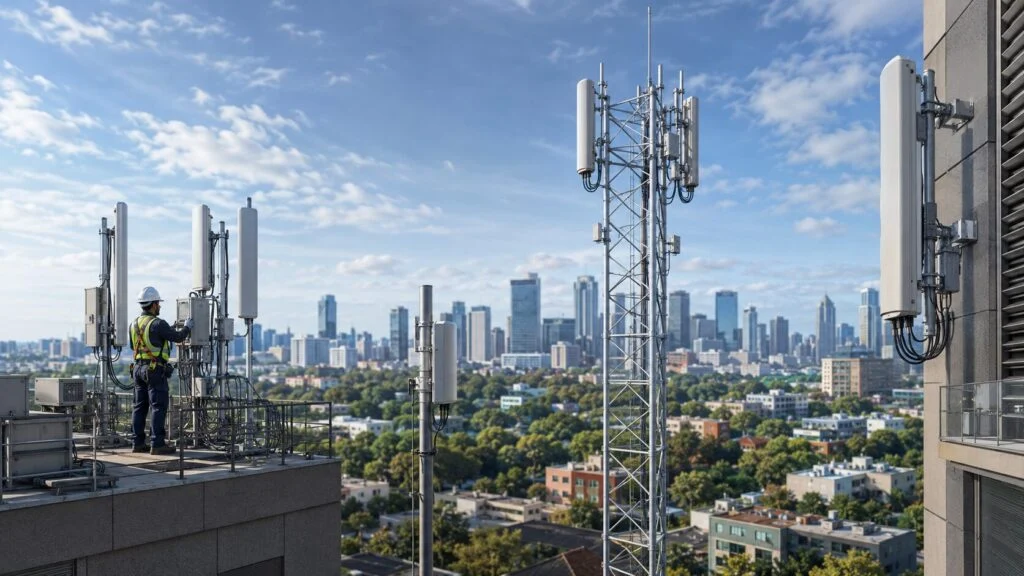
A common specification question is whether a single antenna can cover both sub-6 GHz and mmWave bands. The short answer is no.
The physical size of an antenna element is proportional to wavelength. A 3.5 GHz antenna element is approximately 43 mm long. A 28 GHz element is 5.4 mm long. These cannot share the same physical radiator with acceptable efficiency.

Dual-band 5G base stations use separate antenna modules:
- A macro panel or massive MIMO array for sub-6 GHz (n77, n78, n79, LTE)
- A separate mmWave phased array module for 24 GHz and above
Some integrated base station housings contain both modules in a single enclosure, but the RF paths, antenna arrays, and beamforming controllers remain entirely independent.
Link Budget Example: mmWave FWA
Here is a worked 28 GHz FWA link budget of the kind we run before a site survey. Every loss below comes from the formulas above, so you can recalculate it for your own distance and rain rate:
| Parameter | Value |
|---|---|
| Frequency | 28 GHz (n261) |
| Base station TX power | 23 dBm |
| Base station antenna gain | 25 dBi |
| Base station EIRP | 48 dBm (FCC ceiling: 75 dBm/100 MHz) |
| Free-space path loss (200 m) | 107 dB |
| Rain fade margin (50 mm/h) | 2 dB |
| Pointing, implementation and misc. margin | 8 dB |
| CPE antenna gain | 18 dBi |
| CPE noise figure | 7 dB |
| Received signal strength | -51 dBm |
| Thermal noise floor (100 MHz, NF 7 dB) | -87 dBm |
| SNR | ~36 dB |
| Achievable throughput | 1 Gbps or more with high-order modulation |
Two things in this table matter more than the bottom line.
First, the regulatory ceiling is not what limits the base station. Under the FCC rules for the Upper Microwave Flexible Use Service (47 CFR §30.202), a fixed or base station may radiate up to 75 dBm/100 MHz EIRP. The 48 dBm in this example sits about 27 dB below that. What actually caps EIRP on a real site is heat, power delivery and the enclosure size the city will approve — not the rulebook.
Second, the same rules cap the device far more tightly: 43 dBm EIRP for mobile stations and 55 dBm for transportable stations. Downlink margin is cheap; uplink margin is not. A coverage plan drawn from downlink signal strength alone will always look better than the network feels. For FWA that is the argument for a high-gain, properly aimed CPE antenna. For mobile, it is the argument for a denser grid of smaller cells.
Practical Deployment Checklist
Before specifying a 5G mmWave antenna or base station for a project, verify the following constraints. These are the items that most commonly delay deployments in our experience. For teams comparing fallback hardware, a multi-band MIMO antenna reference can also help frame the anchor-layer side of the design.
- Regulatory EIRP limits: the maximum varies by country, band and station class. In the United States, 47 CFR Part 30 allows 75 dBm/100 MHz for fixed and base stations, 55 dBm for transportable stations and 43 dBm for mobile stations; several European administrations are stricter. Confirm the exact figure before sizing the array — exceeding it is not a compliance option.
- Zoning and visual impact: mmWave small cells are dense. City planning departments frequently impose size, color, and concealment requirements that affect antenna module dimensions.
- Power availability: Active mmWave antennas consume 200 to 500 watts. Legacy street poles often require electrical upgrades to support this load.
- Backhaul capacity: A mmWave cell capable of 1 Gbps per user needs commensurate backhaul. Wireless backhaul at mmWave creates a coverage paradox—where does the backhaul antenna get its signal?
- Fallback coverage layer: Devices lose mmWave signal indoors, behind obstacles, and in rain. A sub-6 GHz coverage layer is mandatory for service continuity. Do not deploy mmWave without it.
- Thermal management: High-density phased arrays generate significant heat. Ensure the mounting enclosure provides adequate ventilation, heat sinking, or active cooling.
Summary

mmWave delivers the capacity 5G promised, but it needs a different deployment model. The antenna is an active beamforming array with RF and baseband inside it, not a passive radiator fed by a remote transceiver. Cells are hundreds of metres wide — not because the link budget runs out, but because clear line of sight does.
A short planning checklist:
- Treat mmWave as a capacity overlay and always pair it with a sub-6 GHz anchor layer.
- Size cells around obstacles and blockage, not around free-space loss.
- Budget rain fade by link length: a couple of dB under 300 m, a design driver past a kilometre.
- Survey the glazing before promising any indoor coverage.
- Check the uplink, not just the downlink, before committing to a cell radius.
- Judge a module on integration, thermal design and beamforming control as much as on element count.
FAQ
What counts as mmWave in 5G?
In 5G NR, mmWave refers to frequency bands above 24 GHz. These bands offer 400 MHz to 800 MHz of contiguous bandwidth, far more than sub-6 GHz allocations.
Why does mmWave rely on beamforming phased arrays?
Free space path loss at 28 GHz is about 18 dB higher than at 3.5 GHz, so arrays of 256 to 1,024 tiny elements provide 20 to 30 dBi of gain and narrow 3 to 10 degree beams to close the link within regulatory EIRP limits.
How far does a 5G mmWave antenna reach?
Dense urban cells are typically 100 to 300 m and FWA sectors run to roughly 500 m, with multi-kilometre links possible in clear line of sight. The practical limit is obstruction rather than free-space path loss: at 28 GHz the loss grows only about 30 dB between 200 m and 6 km.
Can a single antenna cover both sub-6 GHz and mmWave bands?
No. Element size is proportional to wavelength (about 43 mm at 3.5 GHz versus about 5.4 mm at 28 GHz), so dual-band base stations use separate sub-6 and mmWave antenna modules with independent RF paths.
Why must mmWave always be paired with a sub-6 GHz layer?
mmWave signals are degraded by rain and blocked by walls, foliage, and even glass, so a sub-6 GHz anchor layer is mandatory for service continuity. Treat mmWave as a capacity overlay, not a coverage foundation.
Related Articles and Antenna Options
- Read more: Understanding MIMO and Beamforming in 5G Antennas
- Read more: 5G Outdoor Antenna Types Compared
- Read more: 5G Small Cell and DAS antenna solutions
- Related product or next step: flat panel antenna reference for sub-6 deployment comparisons
- Related product or next step: multi-band MIMO antenna reference for anchor-layer planning
- Related product or next step: request a project consultation
Ask our AI antenna assistant. Enter a keyword or question for a free answer based on this article, Global RF Tech content, and general antenna/RF knowledge.
Do not submit confidential or personal information. Privacy Policy




