
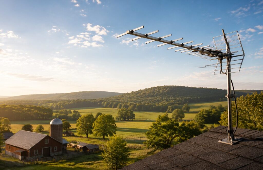
The best outdoor TV antenna for rural areas is the one matched to your tower distance, tower direction and local frequency bands — not the one with the biggest mileage claim on the box.
Short answer
- Start with your tower list, not a product page. The FCC’s DTV Reception Maps show which stations reach your address, and the predictions assume an outdoor antenna about 30 feet above ground.
- Towers within roughly 30 miles and spread over several directions: a multi-directional or omnidirectional outdoor antenna is usually enough.
- Towers 50 miles or more away in roughly one direction: a high-gain directional antenna (Yagi or large bowtie), carefully aimed.
- Check the bands. If your local stations sit on Hi-VHF (channels 7–13), a UHF-only antenna will never receive them, whatever the mileage rating says.
- Leave margin. Cable runs, splitters and connectors can cost more decibels than the extra “range” you paid for.

Rural reception is harder for two reasons: you are farther from the transmitter, and something is usually in the way — a ridge, a tree line, metal roofing. An indoor antenna rarely fixes either one. Below is the decision path: what range ratings really mean, how to pick gain and pattern, which bands to verify, how to budget the signal you lose inside the house, and the installation mistakes that quietly cost channels.
Why a “long-range” antenna may not fix rural reception
The mileage number is marketing, not a measurement
There is no industry test that a “200-mile” label has to pass, so the number tells you where a model sits in a brand’s own lineup — nothing more. You can sanity-check it yourself with free-space path loss (FSPL), the loss a signal takes just by spreading out over distance:
FSPL (dB) = 20 × log10(d) + 20 × log10(f) + 32.45 (d in km, f in MHz)
The useful part is the shape of that formula: every doubling of distance adds about 6 dB, and ten times the distance adds about 20 dB (free-space path loss, based on ITU-R P.525).
| Distance to tower | Extra free-space loss vs. 15 miles | Practical reading |
|---|---|---|
| 15 miles | 0 dB (reference) | Most antennas work here |
| 30 miles | about 6 dB | Needs a real outdoor mount |
| 60 miles | about 12 dB | Directional antenna, clean path |
| 120 miles | about 18 dB | Rarely reliable on flat terrain |
These are engineering estimates for an ideal clear path, not measured field results. Read them as a scale: going from a 60-mile claim to a 200-mile claim implies roughly 10 dB of extra performance, so ask the manufacturer for the published gain curve and check whether the antenna actually delivers it across the channels you need.
Terrain often outweighs distance
Hills, tree lines, buildings and metal surfaces block or scatter TV signals, and reflections arriving a fraction of a microsecond late (multipath) can confuse a tuner even when raw signal strength looks fine. A house 50 miles from the tower with a clear view can easily beat a house 30 miles away behind a ridge.
Receiving a signal is not the same as watching it
Digital TV has a cliff edge: the picture is perfect until the tuner can no longer separate signal from noise, and then the channel is simply gone. There is no “snowy but watchable” middle ground. A long-range antenna also collects more noise and more interference from every direction it is pointed, so what matters is the margin between your signal and everything else — not the raw distance it can theoretically reach.
How to choose the best outdoor TV antenna for rural areas
Step 1: Map your towers before you shop
Enter your address in the FCC’s DTV Reception Maps and write down, for every station you want:
- distance in miles
- compass heading
- RF channel number (not the channel number on screen)
Two details make this list worth more than any buying guide. First, the FCC’s predictions assume an outdoor antenna roughly 30 feet above ground, which is exactly the rural install you are planning — so the color coding is a fair starting point rather than an optimistic one. Second, RF channel numbers tell you which bands you need, and that decides the physical size of the antenna.
Also worth knowing before you climb the roof: the FCC’s Over-the-Air Reception Devices (OTARD) rule limits restrictions on TV antennas installed in areas under your exclusive use or control. Local safety and permitting rules can still apply, especially to tall masts.
Step 2: Match the pattern to your tower map
| Your situation | Antenna type | What to watch |
|---|---|---|
| Towers 50+ miles away, all in one heading | High-gain directional (Yagi, large bowtie) | Aim within a few degrees; a rotator helps if a second market matters |
| Towers within ~30 miles, several headings | Omnidirectional or multi-directional | Lower gain, so keep the cable run short |
| Two tower clusters far apart | Two directional antennas plus a combiner, or a rotator | Combining two antennas can create nulls; test channel by channel |
| One strong local cluster plus one distant station | Directional aimed at the distant one | The strong local signals usually still come in off-axis |
A directional antenna does two jobs at once: it adds gain toward the tower and rejects noise from the sides and back. That rejection is often what actually fixes a marginal channel. See our guide to high-gain antennas for how gain and beamwidth trade off against each other.

Step 3: Check the bands before you check the gain
After the US spectrum repack, broadcast TV lives in three blocks: VHF Low (channels 2–6), VHF High (channels 7–13) and UHF (channels 14–36, 470–608 MHz) (Pan-American television frequencies).
| Band | RF channels | Frequency | Wavelength | Half-wave element |
|---|---|---|---|---|
| VHF Low | 2–6 | 54–88 MHz | about 3.4–5.6 m | about 67–110 in |
| VHF High | 7–13 | 174–216 MHz | about 1.4–1.7 m | about 27–34 in |
| UHF | 14–36 | 470–608 MHz | about 0.49–0.64 m | about 10–13 in |
Antenna elements scale with wavelength, and that is the part spec sheets hide. A resonant element for channel 10 is roughly 30 inches; for channel 30 it is about a foot. So a compact panel or a small bowtie array can be excellent on UHF and still have almost no usable gain on VHF High — and in rural areas the network affiliates on channels 7–13 are exactly the ones people report losing. If your tower list contains any RF channel below 36 that falls in the VHF ranges above, insist on a model with dedicated VHF elements or a VHF add-on kit, and look for a published gain figure in that band, not just “UHF/VHF compatible”.

Step 4: Choose a height you can live with
Higher usually means a cleaner line of sight over trees and roof ridges, and it is the single most effective free upgrade. But height has costs: longer cable, more wind load, harder maintenance, more lightning exposure. Mount as high as you need to clear the obstacle in front of you, then stop. A typical rural install lands about 20–30 feet above ground, or a few feet above the roof peak — and if you can reach the antenna again next year without renting equipment, you will actually re-aim it when a station changes channel.
Step 5: Budget the signal you will lose indoors
The antenna is only the first item in a chain. Split the feed to several TVs and the losses add up fast. Industry limits for passive splitters (ANSI/SCTE 153, Class 2 devices) put a two-way splitter at 4.0 dB or less and a four-way at 7.8 dB or less across the 400–600 MHz range, close to the theoretical minimum of 10 × log10(N) — 3.01 dB for two ports and 6.02 dB for four.
| Item in the chain | Typical budget | Notes |
|---|---|---|
| Coax run | Check the cable’s published dB per 100 ft at 600 MHz | Use RG6, not RG59, for long runs |
| 2-way splitter | up to 4.0 dB | Theoretical floor 3.01 dB |
| 4-way splitter | up to 7.8 dB | Theoretical floor 6.02 dB |
| Poor connectors, adapters, sharp bends | Varies, easily a few dB | Compression connectors on RG6 |
Compare that budget with Step 1. A four-way splitter alone costs about the same as doubling your distance to the tower in free-space terms. If you need four outlets in a weak-signal location, plan a mast-mounted preamplifier with a low noise figure from the start — or feed one TV directly and use a network tuner for the rest.

Directional link planning
Need gain and beamwidth matched to your link?
Tell us the link distance, target band, mounting height and coverage direction. We can help compare Yagi, panel, sector and LPDA antenna options.
Installation tips
- Assemble the antenna on the ground, and never work on a wet or windy roof or near power lines.
- Point a directional antenna at the strongest station in your target cluster, then rescan.
- Adjust in small steps — a few degrees of heading, then a foot of height — and rescan after each change. Use your TV’s signal-strength meter rather than the picture.
- Check the weakest channel you care about, not the strongest. That one sets your real margin.
- Weatherproof every outdoor connection and leave a drip loop so water runs away from the connector.
- Rescan a few times a year. Stations do change RF channels, and the on-screen channel number stays the same when they do.

Common mistakes that cost channels
Ignoring the cable and the connectors
A long run of thin or aged coax can undo the gain you paid for. Use RG6 for outdoor and long indoor runs, keep the run as short as routing allows, use compression connectors rather than push-on adapters, and avoid stacking barrel adapters.
Skipping the ground
A metal antenna and mast on a roof collects static charge and raises the stakes during nearby lightning. In the US, NEC Article 810 requires the mast and the lead-in to be bonded to the building’s grounding electrode system: the bonding or grounding electrode conductor must be no smaller than 10 AWG copper (or 17 AWG copper-clad steel or bronze), and if a separate ground rod is used it must be bonded to the power grounding electrode system with at least a 6 AWG conductor (NEC Article 810 overview). Keep the ground run short and direct, follow your local code, and use a licensed electrician if you are unsure.
One splitter too many
Every passive split costs signal on all outputs, whether or not a TV is connected. Terminate or remove unused outputs, use the smallest splitter that covers your rooms, and re-check the weak channels after any change to the distribution.
Over-amplifying
An amplifier raises signal and noise together. It helps with long cable runs and splitter loss; it cannot rebuild a signal the antenna never captured, and too much gain can overload a tuner in the presence of strong nearby transmitters. If you use one, mount it near the antenna, choose a low noise figure, and pick the lowest gain that solves your loss budget.
FAQ
How high should an outdoor TV antenna be?
High enough to clear the obstacles between you and the tower — commonly about 20–30 feet above ground in rural installs, or a few feet above the roof peak. Beyond that, extra height mostly adds cable loss, wind load and risk. Note that the FCC’s coverage predictions themselves assume roughly a 30-foot outdoor antenna, so that height is a reasonable planning target.
Do I need an amplifier?
Only to make up for losses after the antenna: long coax, multiple splitters, several TVs. If a channel is missing because of aim, height or blockage, an amplifier will not bring it back.
Why do I get some channels but not others?
Usually one of three reasons: the missing stations transmit from a different direction, they sit in a band your antenna does not really cover (most often VHF High, channels 7–13), or their signal is simply below your margin. Check the RF channel of each missing station on the FCC map before buying anything new.
Do I need a new antenna for NextGen TV (ATSC 3.0)?
No. ATSC 3.0 uses the same VHF and UHF channels as ATSC 1.0, so the antenna you install today keeps working; what you need is a compatible tuner. Deployment has already reached a large share of US households and all of the top 25 markets, but coverage is still market by market — check current ATSC 3.0 deployments for your area.
Why do channels drop out on warm summer nights?
Temperature layers in the lower atmosphere can bend UHF signals back toward the ground and carry them far past their normal range. ITU-R P.834 defines the condition: a duct forms where the vertical refractivity gradient falls below −157 N/km. The result is co-channel interference from distant transmitters that appears for minutes or hours and then disappears. A narrower-beam directional antenna aimed away from the interfering path usually helps more than extra gain.
Ready to specify a product?
Get product suggestions and quotation details for your application.
Tell us the link distance, target band, mounting height and coverage direction. We can help compare Yagi, panel, sector and LPDA antenna options.
Ask our AI antenna assistant. Enter a keyword or question for a free answer based on this article, Global RF Tech content, and general antenna/RF knowledge.
Do not submit confidential or personal information. Privacy Policy




