

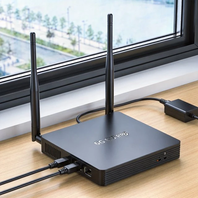
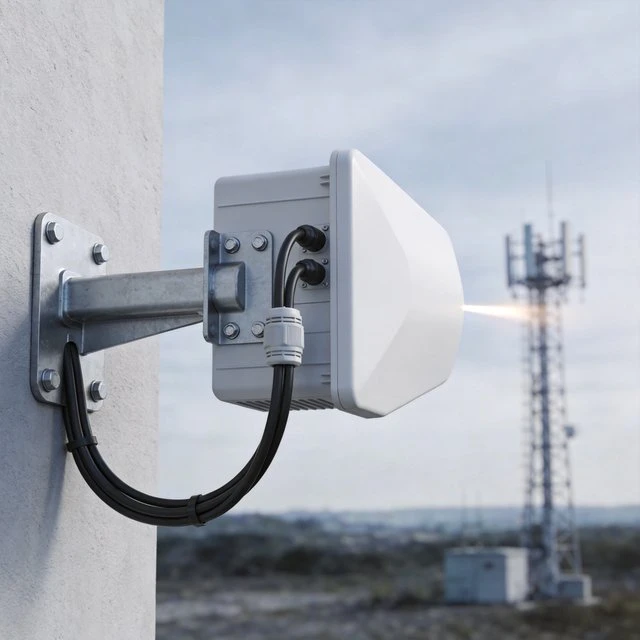
Telecom CPE terminals (indoor gateways, rugged enterprise routers, outdoor units) are a special class of “terminal antenna” problem because the device is often installed by non-RF specialists, yet antenna placement can swing performance by orders of magnitude. Unlike phones, CPE can justify larger external antennas and longer cables to reach optimal mounting points (windows, rooftops, poles). This shifts the design objective from “fit inside the enclosure” to “make installation repeatable and robust.” A directional, outdoor 2 x 2 MIMO antenna datasheet provides a concrete example: coverage spans major cellular bands from 698-960 MHz through 3400-3800 MHz and includes a stated 11 dBi peak gain, with two SMA-terminated ports and 5 m cables-an architecture optimized for fixed wireless placement and aiming. Such antennas are often paired with routers that expose multiple external cellular antenna connectors. A ruggedized 5G router datasheet, for instance, specifies four SMA cellular antenna connectors, reflecting a common requirement to support diversity and/or 4×4 MIMO configurations at the terminal. Testing and deployment guidance from test-and-measurement vendors highlights the system-level impact of CPE antenna gain on coverage, reinforcing why installers focus on mounting height, aiming, and cable loss management rather than internal antenna tuning. At the standards level, cellular terminal performance relates to OTA test methodologies and conformance expectations, especially where radiated metrics (TRP/TRS) are used as part of performance verification.
An ETSI specification explicitly scopes UE TRP/TRS conformance testing methodologies for FR1, illustrating how radiated performance is operationalized for terminals. Deployment quality is usually limited by four practical failure modes. First, poor antenna placement (indoors behind attenuation, close to metal obstructions) reduces signal and increases interference coupling. Second, low-quality or excessively long cables add insertion loss, partially negating antenna gain. Third, incorrect polarization and MIMO port mapping can reduce effective spatial-stream performance. Fourth, regulatory limits on EIRP and spurious emissions (and local installation codes) constrain what amplifiers or high-gain antennas are allowable in a given region. The central best practice is therefore procedural: define an installer workflow that treats antenna installation as a measurable process (RSSI/RSRP/SINR checks, throughput checks, incremental aim adjustment) rather than a hope-based setup
Target Audience
- ISP/CSP CPE engineers
- enterprise network installers
- FWA equipment integrators
- field installation teams
Key Technical Points
- External MIMO antennas trade enclosure constraints for installation variability
- multi-port routers enable MIMO/diversity
- cable loss and aiming are first-order variables
- TRP/TRS and OTA thinking still matter for terminal verification
Practical Use Cases
- Rural/home FWA
- temporary construction-site connectivity
- enterprise failover routers
- smart city cabinets with external antennas
Relevant Standards and Protocols
- Cellular NR/LTE terminal requirements (ETSI/3GPP)
- OTA TRP/TRS test methodologies
- regional regulatory constraints for unlicensed radios if Wi-Fi is integrated (e.g., ETSI EN 301 893 for 5 GHz RLAN)
Typical Hardware Examples
- Poynting XPOL-2-5G directional 2 x 2 MIMO antenna with published band coverage, gain, cables, and connectors
- Ericsson Cradlepoint R980 ruggedized router with four SMA cellular antenna connectors
- Rohde & Schwarz FWA CPE material highlighting coverage sensitivity to terminal antenna gain
Deployment Considerations
- Site survey
- outdoor mounting and grounding
- cable length control
- correct polarization and port mapping for MIMO
- compliance with local transmit/EIRP limits
- weatherproofing and strain relief
Related reading: if your project extends from router-side hardware to full in-building coverage, see our distributed antenna system (DAS) guide. For choosing the antenna itself, see our 5G MIMO antenna picks by use case.
Interference environment
Need an antenna matched to a high-interference project?
Tell us the frequency range, installation space and interference scenario. We can suggest suitable anti-jamming or specialty antenna options.
FAQ
Why do FWA routers use external MIMO antennas instead of internal ones?
CPE can justify larger external antennas and longer cables to reach optimal mounting points such as windows, rooftops, or poles. This shifts the design objective from fitting inside the enclosure to making installation repeatable and robust.
How many antenna ports do 5G FWA routers typically provide?
Ruggedized 5G routers commonly specify four SMA cellular antenna connectors, reflecting the requirement to support diversity and/or 4×4 MIMO configurations at the terminal.
What most commonly limits FWA deployment quality?
Four practical failure modes: poor antenna placement, low-quality or excessively long cables that add insertion loss, incorrect polarization or MIMO port mapping, and regulatory limits on EIRP and spurious emissions.
What is the best practice for installing FWA antennas?
Treat antenna installation as a measurable process, with a site survey, correct aiming, and RSSI, RSRP, SINR, and throughput checks plus incremental aim adjustment, rather than a hope-based setup.
Related: for multi-antenna coverage inside large buildings rather than a single FWA router, see our in-building DAS antenna options.
Related: choosing external antennas for an LTE or 5G FWA router? See how to choose an antenna for your LTE or 5G router.
Ready to specify a product?
Get product suggestions and quotation details for your application.
Tell us the frequency range, installation space and interference scenario. We can suggest suitable anti-jamming or specialty antenna options.


