

A lot of “weak signal” problems are not weak signal at all. They are polarization mismatch. The power is there and the band is right, but the receiving antenna is not lined up with the field the transmitter sends, so part of the link simply disappears. Get polarization wrong and even good hardware underperforms.
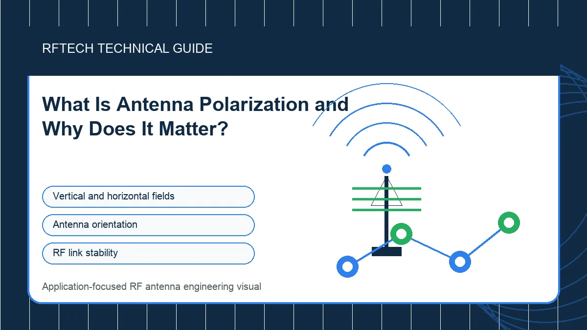
Antenna polarization is the orientation of the electric field an antenna radiates, in other words how the wave is oriented in space. The common forms are linear (vertical or horizontal), slant (usually ±45°) and circular (right- or left-hand). The definition is not the hard part. The question that decides your link is simpler: do both ends share the same polarization?
Quick answer
Match polarization at both ends before you argue about gain. Most terrestrial cellular, IoT and point-to-point links are linear, and usually vertical, so specify vertical on both sides. GNSS has to be RHCP, because GPS L1 (1575.42 MHz) is transmitted right-hand circular. MIMO uses ±45° dual-slant, which keeps two orthogonal linear paths isolated inside one housing. For two linear antennas the loss follows cos²θ: about 3 dB at 45°, about 6 dB at 60°, and a theoretical null at 90° (20–30 dB in practice). Linear to circular always costs about 3 dB. If you check only one thing before installation, check the final mounting orientation.
What is antenna polarization?
Polarization is the direction in which the electric field of the radiated wave oscillates. If the field stays in one plane, the antenna is linearly polarized. If it rotates as the wave travels, it is circularly polarized. Elliptical polarization sits between the two. For industrial, IoT, GNSS and cellular work, the practical split is linear vs slant vs circular.
Linear polarization

Linear means the field stays in one fixed orientation, usually vertical or horizontal. Most terrestrial antennas are vertical. RFTECH’s GL7027V6 fiberglass omni and GL-DY7038V11 LPDA are both vertical, so they pair directly with vertically polarized radios. Some antennas let you choose. The GL-DYU4YG3S UHF Yagi, for example, can be mounted vertical or horizontal. The rule stays the same: both ends should match.
Circular polarization
Circular means the field rotates as the wave travels, either right-hand (RHCP) or left-hand (LHCP). Because the field rotates, it tolerates orientation changes between the two ends. That is why GNSS antennas use it: satellites move across the sky, and the receiver can sit at any angle. RFTECH’s GL-DY225D GNSS antenna is RHCP at 1575.42 MHz (GPS L1) for exactly that reason.
Polarization by antenna type
It is easiest to see with real parts:
| Polarization | What it is | RFTECH example |
|---|---|---|
| Vertical linear | Field fixed, vertical | GL7027V6 omni; GL-DY7038V11 LPDA |
| Horizontal / selectable | Field fixed, horizontal (or chooseable V/H) | GL-DYU4YG3S Yagi (V or H) |
| ±45° dual-slant | Two slanted linear paths in one housing, for MIMO | GL-DY7040S4707 (4-port); GL1727D-15 panel |
| Circular (RHCP) | Field rotates, right-hand | GL-DY225D GNSS (1575.42 MHz) |
Which polarization should you use?
Use the application, not the datasheet headline, to decide:
| Application / condition | Polarization to specify | Why | RFTECH example |
|---|---|---|---|
| Cellular / IoT infrastructure, fixed install | Vertical linear | Existing network side is vertical; matching is what matters | GL7027V6 omni |
| Point-to-point directional link | Linear, same orientation both ends | Orientation is controllable, so use the lower-loss linear path | GL-DY7038V11 LPDA; GL-DYU4YG3S Yagi (V or H) |
| GNSS / satellite receive, moving or arbitrary attitude | RHCP | Satellite geometry keeps changing; GPS transmits RHCP | GL-DY225D (1575.42 MHz) |
| MIMO router, gateway or sector, multiple streams | ±45° dual-slant | Orthogonal paths give port-to-port isolation for separate streams | GL-DY7040S4707 (4-port); GL1727D-15 panel |
| Cable routing or bracket forces a rotation | Re-check before locking the design | Rotating a linear antenna changes polarization alignment | Choose an antenna that can be mounted in the required orientation |
Why polarization matters in real projects
Match the band but miss the polarization and efficiency drops fast. The energy is still in the air; the receiver just is not lined up to absorb it. For two linear antennas the theoretical loss is the cosine-squared of the angle between them:
| Angle between the two linear antennas | Theoretical loss (20·log₁₀|cos θ|) | What it means on the link |
|---|---|---|
| 0° | 0 dB | Aligned — the case you should design for |
| 15° | ≈ 0.3 dB | Small install tolerance, usually acceptable |
| 30° | ≈ 1.25 dB | Noticeable at the cell edge |
| 45° | ≈ 3 dB | Half the received power |
| 60° | ≈ 6 dB | Roughly like losing three quarters of your power |
| 90° | Infinite in theory; typically 20–30 dB in practice | Fully cross-polarized — close to a dead link |
| Linear to circular (any angle) | ≈ 3 dB | Fixed penalty, does not improve by rotating |
Conditions: far-field, co-located frequency band, ideal single-path propagation, and antennas with no cross-polar leakage.
Limitation: real installations never reach infinite isolation. Reflections from ground, walls, vehicles and metal structures rotate part of the field, so a 90° cross usually measures 20–30 dB of discrimination rather than a total null. Treat the table as a design budget, not a measured result for your site — polarization loss also adds on top of cable loss, mismatch and pattern misalignment.
On site this looks like low received signal, unstable links, poor throughput and weak cell-edge coverage. Teams often chase it as a power problem and lose days. That is why orientation belongs in the design, not in the install notes.
Linear polarization in common wireless systems
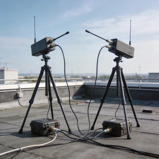
Most terrestrial links use linear polarization because the installation is fixed enough to control orientation. If both ends are designed vertical, rotating one end horizontal creates a major mismatch. It matters most in four cases: point-to-point directional links, sectorized infrastructure, IoT gateways with fixed endpoints, and multi-antenna setups where element orientation drives isolation. So when you compare antennas, check the intended mounting orientation alongside gain and band.
Circular polarization and where it helps
Circular polarization comes up in satellite and GNSS work for one reason: the relative orientation of the two ends keeps changing, and a rotating field handles that better than a fixed linear one. But circular is not automatically better. It helps only when the application needs it. Used without a reason, it complicates design, sourcing and matching. A GNSS patch like the GL-DY225D is RHCP because GPS signals are transmitted RHCP, and matching that is the whole point.
What is polarization mismatch?
Polarization mismatch means the receive antenna is not aligned to the field of the incoming signal. The classic case is one antenna vertical and the other horizontal in a linear link. Everything else can look correct and the link still underperforms. It usually creeps in for one of four reasons: an antenna is mounted the wrong way, elements in a multi-antenna system are positioned inconsistently, a team assumes “any orientation works”, or equipment is moved without a re-check.
How to check whether polarization is the actual problem
On a signal bar, polarization mismatch looks exactly like a bad cable or a detuned antenna. Separate them in this order:
- Read S11/VSWR at the antenna port. A mismatch in polarization does not change VSWR — if VSWR is bad, you have a matching, cable or connector problem instead.
- Note the baseline RSSI/SNR (and throughput or packet loss if the radio reports it) without touching anything else.
- Rotate only the receiving antenna by 90° and re-read RSSI. A swing of several dB up or down points to polarization; almost no change points elsewhere.
- Confirm the far end’s specified polarization from its datasheet, not from how it looks on the mast.
- For GNSS, check TTFF and satellites in view instead of RSSI, and confirm the antenna is RHCP.
- Only after that, investigate cable loss, connector gender/type, ground plane and enclosure effects.
Limitation: step 3 assumes the link is otherwise stable during the test. On a fading or mobile link, repeat the measurement several times before concluding anything.
How polarization affects MIMO and advanced systems
In MIMO, polarization is not a detail. It is part of how the system works. Dual-slant ±45° designs use two orthogonal linear paths on purpose, so two data streams can share one antenna and stay isolated. RFTECH’s GL-DY7040S4707 shows this clearly: a 4-port ±45° antenna covering 698–960 / 1710–2700 / 3400–4000 MHz, with a front-to-back ratio of ≥ 20 dB. Those orthogonal polarizations are what keep the four streams apart. For the wider picture, see MIMO and beamforming in 5G antennas. When you compare MIMO antenna options, check element orientation, port count and the device’s actual mounting direction.
Common installation mistakes
Rotating the antenna without checking orientation
Installers rotate an antenna to make the cable reach or the bracket fit. They rarely realize they have also changed its polarization alignment.
Assumptions across teams
Mechanical, RF and field teams each assume someone else confirmed the orientation. That gap is where most avoidable mismatch happens.
Treating all antennas as interchangeable
Two antennas on the same band can behave very differently if their polarization intent differs. A vertical omni and a ±45° panel are not drop-in swaps.
A practical checklist before deployment
- What polarization does the transmitting side use?
- Will the receiving side hold a fixed orientation?
- Is the device static or in motion?
- Does the application benefit from diversity or cross-polarized (±45°) elements?
- Is the install team told the exact final orientation?
If any answer is unclear, pause before locking the antenna configuration.
Write the final orientation into the installation drawing and the site photo checklist, not only into an email. Most avoidable mismatch happens between the RF decision and the person holding the bracket.
Make polarization a first-order requirement
Polarization is the orientation of the radiated field, and whether both ends line up to exchange energy. Treat it as a first-order requirement, alongside band, gain and enclosure. A 45° slip already costs about 3 dB, and a full cross can kill a link. Match vertical to vertical, RHCP to RHCP for GNSS, and use ±45° dual-slant for MIMO. For help matching polarization to a product or deployment, start from the relevant application guidance or request a quote. To get a useful answer in one pass, send:
- frequency band(s) and radio/module used;
- polarization of the other end of the link (or the network you connect to);
- mounting position, orientation and available space, plus whether the device moves;
- connector type and cable type/length;
- environment (indoor, outdoor, vehicle, metal structure) and IP requirement;
- measured S11/VSWR and RSSI if you are troubleshooting an existing link.
Frequently asked questions
What does antenna polarization mean?
It is the orientation of the electric field the antenna radiates. Linear keeps the field in one plane (vertical or horizontal), slant uses an angled linear field (often ±45°), and circular rotates the field (right- or left-hand). Both ends of a link should share the same polarization.
What happens if antenna polarizations do not match?
You lose signal. A 45° offset between two linear antennas costs roughly 3 dB, which is half the power. A full 90° cross can lose 20 dB or more, and linear to circular costs about 3 dB. The link looks weak even though the transmit power and band are fine.
Why are GNSS/GPS antennas circularly polarized?
GPS and other GNSS satellites transmit right-hand circular polarization, and the satellite-to-receiver orientation constantly changes as satellites move. A RHCP antenna like the GL-DY225D (1575.42 MHz) tolerates that far better than a fixed linear antenna would.
What is ±45° (dual-slant) polarization?
Two linear elements set at +45° and −45° in one antenna. Because the two paths are orthogonal, they stay isolated and can carry separate MIMO data streams. That is why MIMO antennas like the GL-DY7040S4707 use ±45°.
How do I confirm a weak link is a polarization problem and not a cable problem?
Check S11/VSWR first — polarization mismatch does not degrade VSWR, so a bad VSWR points to matching, cable or connector issues. If VSWR is fine, rotate one antenna 90° and watch RSSI/SNR: a swing of several dB indicates polarization, while almost no change means you should look at cable loss, ground plane or enclosure effects instead.
Vertical or horizontal polarization — which should I use?
Whichever the other end of the link uses; matching is what matters. Most cellular and IoT infrastructure is vertical, so vertical antennas like the GL7027V6 or GL-DY7038V11 are the common default. Some antennas (e.g. the GL-DYU4YG3S Yagi) let you mount either way to match the existing system.
Ask our AI antenna assistant. Enter a keyword or question for a free answer based on this article, Global RF Tech content, and general antenna/RF knowledge.
Do not submit confidential or personal information. Privacy Policy




