

Outdoor 5G infrastructure subjects antennas to environmental stress that indoor equipment never encounters: wind, rain, thermal cycling, UV degradation, and ice loading. The antenna must survive these conditions while delivering a predictable radiation pattern over a multi-year service life.
We manufacture and supply all four major outdoor 5G antenna categories. This article compares their radiation characteristics, mechanical requirements, and ideal deployment scenarios from a specification and procurement perspective.
1. Directional 5G Antennas
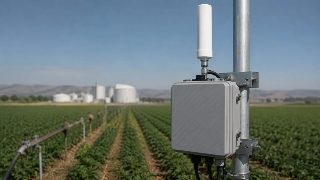
A 5G directional antenna radiates energy in a focused beam, typically with a horizontal beamwidth of 30 to 65 degrees. Energy is concentrated in one direction, resulting in higher gain and longer effective reach than omnidirectional alternatives.
Key Specifications
| Parameter | Typical Range |
|---|---|
| Horizontal beamwidth | 30° – 65° |
| Vertical beamwidth | 7° – 15° |
| Gain | 12 – 20 dBi |
| Front-to-back ratio | >20 dB |
| Common supported bands | n48, n77, n78, n79; LTE B42/B43 |
Best Applications
- Point-to-point backhaul: Connecting two buildings or remote sites where fiber trenching is uneconomical.
- Fixed wireless access (FWA): Serving a cluster of CPE devices from a single tower or rooftop.
- Edge coverage fills: Covering a known highway segment, railway corridor, or industrial zone where macro coverage is weak.
- Interference-sensitive zones: Directing energy away from adjacent licensed spectrum users or co-located systems.
A directional 5g antenna is the correct choice when the coverage target is a known, fixed geographic area and the installation team can aim the antenna precisely during commissioning. The narrow beamwidth demands accurate azimuth alignment; a 10-degree pointing error can place the main lobe outside the intended coverage zone entirely.
2. Panel Antennas
Panel antennas are the most recognizable element of cellular infrastructure. They are a subset of directional antennas with a flat, rectangular form factor and an array of radiating elements behind a reflector plane.
A 5G panel antenna typically uses dipole or patch element arrays. The flat shape reduces wind loading compared to cylindrical or Yagi designs, and the sealed radome provides long-term weather protection.
Panel Antenna Variants
| Variant | Horizontal Beamwidth | Primary Use Case |
|---|---|---|
| Narrow-panel | 30° – 33° | Dense urban macro sectors, capacity layering |
| Standard-panel | 65° | General macro deployment, suburban coverage |
| Wide-panel | 90° | Rural wide-area coverage, highway overlap |
| Dual-band panel | Multiple arrays in one housing | LTE + 5G NR band consolidation |
| Triple-band panel | Three arrays in one housing | Multi-operator or multi-generation co-location |
Modern dual-band and tri-band panels allow operators to consolidate legacy LTE and new 5G NR bands into a single antenna housing. This reduces tower loading, lease costs, and visual impact—factors that matter increasingly in urban zoning reviews.
Mounting Considerations
Panel antennas are typically pole-mounted or wall-mounted using adjustable brackets. For tower installations, the bracket must support:
- Mechanical tilt: Physical adjustment of the antenna downtilt angle during installation.
- Electrical tilt (e-tilt): Remote adjustment via a motorized phase shifter, allowing optimization without tower climbs.
- Azimuth rotation: ±30° or greater adjustment from the mounting orientation.
Wind loading is a critical specification. A standard 2-meter panel antenna presents a wind surface area of approximately 0.3 to 0.4 square meters. At 150 km/h wind speed, the force on the antenna can exceed 300 Newtons. The mounting bracket, pole, and foundation must be engineered for this load with an appropriate safety factor.
3. Sector Antennas
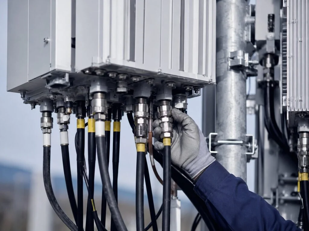
Sector antennas are directional antennas deployed in a circular array to provide full 360-degree coverage around a base station site. The standard macro configuration uses three 120-degree antennas. High-capacity urban sites may use six 60-degree antennas or even twelve 30-degree antennas.
A sectorised 5g antenna is distinguished from a general directional antenna by its beamwidth and vertical pattern shaping. Sector antennas are optimized for 60°, 90°, or 120° horizontal coverage, with a vertical pattern designed to reduce energy waste above the horizon (skyward) and below the effective coverage zone (ground bounce).
Sectorization Strategies
| Sectors per Site | Beamwidth per Antenna | Typical Application |
|---|---|---|
| 3 | 120° | Standard macro cell, rural and suburban |
| 6 | 60° | Urban capacity, highway corridors, rail lines |
| 9–12 | 30° – 40° | Dense urban cores, special events, stadium perimeters |
Higher sectorization increases frequency reuse and system capacity but requires more antennas, more cables, more tower space, and more complex handover management between sectors. The physical tower must also support the additional wind loading.
For sector antenna deployments, horizontal alignment between adjacent sectors is critical. Overlap must be sufficient to prevent coverage gaps during handover but not so wide that it creates excessive inter-sector interference. In our field commissioning experience, a 5- to 10-degree overlap between adjacent sector edges provides the best balance.
4. Omnidirectional Antennas
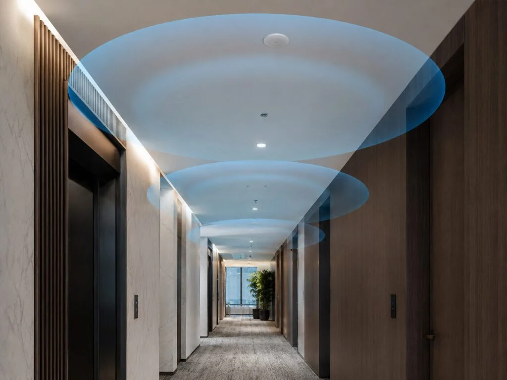
An omnidirectional 5G antenna radiates uniformly in the horizontal plane (360 degrees) with energy concentrated toward the horizon. In the vertical plane, the pattern is toroidal—doughnut-shaped—with a null directly above and below the antenna element.
Key Specifications
| Parameter | Typical Range |
|---|---|
| Horizontal beamwidth | 360° |
| Vertical beamwidth | 7° – 15° |
| Gain | 6 – 12 dBi |
| Pattern | Toroidal |
Best Applications
- Small cell poles: Where 360-degree street-level coverage is required from a single mount point.
- Temporary deployments: Construction sites, event venues, emergency response networks.
- DAS remote units: Outdoor nodes that need to cover a circular area around the mounting location.
- IoT gateway aggregators: Collecting sensor data from devices distributed around a central hub.
Omnidirectional antennas are simpler to install because they do not require azimuth alignment. However, their lower gain and full-circle radiation make them more susceptible to interference from neighboring cells. They are rarely used in dense macro networks but are standard equipment for small cell and private 5G deployments, especially when teams are comparing options like a fiberglass omni antenna.
Comparison Summary
| Feature | Directional | Panel | Sector | Omnidirectional |
|---|---|---|---|---|
| Coverage shape | Narrow pencil beam | Flat directional beam | Wide wedge (60–120°) | 360° circle |
| Typical gain | 15–20 dBi | 12–18 dBi | 10–16 dBi | 6–12 dBi |
| Wind loading | Moderate | Low (flat profile) | Moderate | Low |
| Installation complexity | High (precise aiming) | Medium | Medium | Low |
| Primary application | PTP backhaul, FWA | Macro sector standard | Standard cell site geometry | Small cell, temporary |
| Interference control | Excellent | Good | Moderate | Poor |
Interference environment
Need an antenna matched to a high-interference project?
Tell us the frequency range, installation space and interference scenario. We can suggest suitable anti-jamming or specialty antenna options.
Selection Decision Framework
Use the following logic to narrow the antenna type for your project:
- Is the coverage target a known, fixed zone?
- Yes → Directional or Panel
-
No; coverage surrounds the mounting point → Omnidirectional
-
Does the site need full 360-degree coverage?
- Yes, with multiple simultaneous sectors → Sector array (3, 6, or more)
-
Yes, with a single antenna → Omnidirectional
-
Is this a macro cell or a small cell deployment?
- Macro cell, multi-user, high capacity → Panel or Sector
-
Small cell, localized, lower user density → Omnidirectional or Narrow Panel
-
Is point-to-point backhaul required?
- Yes → High-gain Directional (narrowest beamwidth available)
Environmental and Mechanical Requirements
An outdoor 5g antenna must survive conditions far beyond RF stress. When specifying, verify the following against your deployment environment:
- IP rating: IP65 minimum for standard outdoor rain and dust exposure. IP67 or IP68 for submerged, coastal, or flood-prone locations.
- UV resistance: The radome material—typically fiberglass-reinforced plastic or UV-stabilized polymer—must resist degradation from prolonged solar exposure. Uncoated ABS plastic will yellow and crack within 18–24 months in equatorial or desert environments.
- Temperature range: Standard commercial grade is -30°C to +60°C. Industrial and infrastructure deployments require -40°C to +70°C or wider.
- Wind survival: The antenna must be rated for the maximum regional wind speed with at least a 1.5x safety margin. In hurricane zones, this means 250+ km/h survival ratings.
- Salt fog resistance: Essential for coastal, offshore, and marine installations. ASTM B117 salt spray testing for 96 hours or more is a common qualification standard.
- Connector sealing: All RF connectors must have weather boots, heat-shrink seals, or be located inside a sealed junction box. Unsealed SMA connectors exposed to rain will corrode and degrade return loss within months.
Summary
Directional and panel antennas dominate macro and FWA deployments where gain and interference control are paramount. Sector antennas provide the foundational geometry of conventional cellular networks. Omnidirectional antennas serve small cells, temporary sites, and circular coverage zones. If the project later moves into denser pole or facade rollouts, the deployment tradeoffs start to overlap with 5G small cell antenna solutions.
The correct choice depends on coverage shape, device density, mounting constraints, and environmental exposure. Start with the coverage target on a map, then match the antenna pattern to the geography. Specify environmental ratings at the outset; retrofitting an antenna for harsh-environment compliance after deployment is always more expensive than selecting the right hardware initially.
FAQ
What are the main outdoor 5G antenna types?
Directional, panel, sector, and omnidirectional antennas. They differ in beam pattern, gain, wind loading, and the coverage shape they are best suited to.
When should I choose a directional or panel antenna versus an omnidirectional one?
Choose directional or panel antennas when the coverage target is a known, fixed zone such as point-to-point backhaul, FWA, or an edge coverage fill. Choose omnidirectional when coverage must surround the mounting point, as with small cells or temporary sites.
How does a sector antenna differ from a plain directional antenna?
Sector antennas are directional antennas deployed in a circular array for full 360-degree coverage, typically three 120-degree antennas, with a vertical pattern shaped to reduce energy waste above the horizon and below the coverage zone.
What environmental ratings should an outdoor 5G antenna meet?
IP65 minimum (IP67 or IP68 for submerged or coastal sites), a UV-resistant radome, a temperature range such as -30 C to +70 C, and a wind survival rating with at least a 1.5x safety margin.
If you are still deciding between full-circle coverage and a focused link, start with the omni vs directional antenna pattern guide, then come back to compare outdoor 5G antenna types.
Related Articles and Antenna Options
- Read more: What Is Antenna Gain?
- Read more: 5G Small Cell and DAS antenna solutions
- Read more: 5G mmWave antenna deployment
- Related product or next step: directional LPDA antenna example
- Related product or next step: flat panel antenna example
- Related product or next step: fiberglass omni antenna example
Ready to specify a product?
Get product suggestions and quotation details for your application.
Tell us the frequency range, installation space and interference scenario. We can suggest suitable anti-jamming or specialty antenna options.
Ask our AI antenna assistant. Enter a keyword or question for a free answer based on this article, Global RF Tech content, and general antenna/RF knowledge.
Do not submit confidential or personal information. Privacy Policy




