A folded dipole array antenna combines several folded dipole elements with a feed network to shape coverage from a fixed radio site. Before choosing one, match the operating channels, horizontal coverage pattern, vertical beamwidth and mounting limits. A higher gain number alone does not tell you how far a radio link will work.
For a 150 MHz project, the GL-DY150I four-bay folded dipole array provides a documented example: 8.8 dBi omnidirectional gain or 11.8 dBi directional gain. For a 400 MHz project, the GL400IA four-dipole array lists 9 dBi omnidirectional or 12 dBi directional gain. The useful comparison starts with your radio system and coverage map.
What is a folded dipole array antenna?
A folded dipole uses two connected parallel conductors. A base-station array combines multiple elements, often stacked vertically. The feed network sets their relative phase, while element spacing and the supporting mast affect the radiation pattern.
The Chinese trade term “环阵天线” is used for this style of exposed folded dipole array. In English, specify a folded dipole array antenna and the number of bays. A circular arrangement of independent antennas is a different design; the word “ring” alone does not identify the required antenna.
Stacking elements can increase gain near the intended coverage angle by narrowing the vertical pattern. It does not create extra transmitter power. The benefit depends on whether the users actually lie within that pattern.
Omnidirectional and directional gain describe different coverage
An omnidirectional configuration aims to serve users around the site in the horizontal plane. A directional configuration concentrates coverage toward part of the service area. Mast diameter, element position and spacing affect the installed pattern, so use the specified mounting arrangement and request its radiation plots.
- Users around a central site: start with the omnidirectional arrangement and examine coverage in each required direction.
- Users mainly on one side of a site: assess the directional arrangement, including its beamwidth and coverage behind the antenna.
- Users both below the tower and farther away: examine the vertical pattern and any available downtilt option before adding gain.
On GL-DY150I, 11.8 dBi is the directional figure; 8.8 dBi is the omnidirectional figure. They describe different configurations, not two simultaneous performance levels and not a software-controlled mode switch. Confirm the required arrangement when ordering. Our omnidirectional versus directional antenna guide explains the broader coverage trade-off.
Why 3 dB more gain does not mean twice the range
A 3 dB gain increase corresponds to approximately twice the power density in the direction being compared, with transmitter power and other conditions unchanged. It does not double the communication distance.
Under an ideal free-space model, a 3 dB link-budget improvement allows approximately 1.41 times the distance at the same received-power threshold. Doubling distance adds about 6 dB of free-space path loss. These are calculation examples, not field-range promises: terrain, antenna heights, obstructions, interference and fading can dominate the result.
Feeder loss matters too. If the antenna provides 3 dB more gain but the new feeder adds 3 dB of loss, the improvement is cancelled in that simplified link budget. Check the uplink as well as the downlink; a base station reaching a handheld does not prove that the handheld can reach back.
Keep gain units consistent. dBi uses an isotropic reference; dBd uses a half-wave dipole reference. The usual conversion is dBi = dBd + 2.15. Compare values for the same frequency, mounting arrangement and reference unit. See what antenna gain means for the underlying terms.
150 MHz and 400 MHz: match the radio before comparing gain
A 150 MHz antenna and a 400 MHz antenna are not interchangeable simply because they have similar gain. Your operating channels must match the selected antenna configuration. Confirm both transmit and receive frequencies for a repeater or duplex system.
For comparable designs, the lower-frequency array generally needs larger elements and more installation space. The actual product dimensions and load limits, rather than the frequency label alone, determine whether it fits the site.
150 MHz example: GL-DY150I
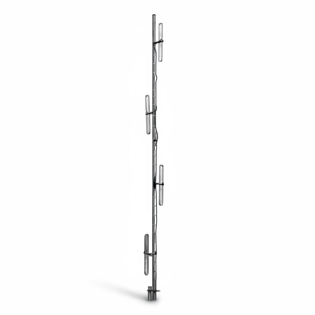
The GL-DY150I product specifications list a 134–173 MHz frequency range, 8 MHz bandwidth, vertical polarization and 50 Ω impedance. The recorded gain is 8.8 dBi omni or 11.8 dBi directional, with a 13.5° vertical beamwidth. Maximum input power is 500 W; length is 5.5 m and weight is 8 kg. UHF or N-female connector options are listed.
Frequency range and bandwidth are separate specifications. Do not interpret the 134–173 MHz family range as a guarantee of the specified match across that entire span in one supplied unit. Give the supplier your exact channel plan and request the applicable tuned bandwidth, VSWR curve and radiation pattern.
400 MHz example: GL400IA
The GL400IA four-dipole UHF antenna is listed on the GL400 comparison page alongside GL400DQ-2 and GL400IA-2. Select GL400IA when reviewing its specifications or requesting a quotation: the other models have different array sizes, bandwidths, power ratings and dimensions.
GL400IA lists 400–480 MHz, 16 MHz bandwidth, 9 dBi omnidirectional or 12 dBi directional gain, 13° vertical beamwidth and 100 W maximum power. Its listed dimension is 250 cm and weight is 8 kg. These values belong to GL400IA; do not transfer them to another GL400 model.
For both frequency bands, confirm the intended coverage configuration and operating channels before using a gain figure in the link budget.
Five checks before specifying the array
- Write down the channel plan. Include transmit and receive frequencies, channel spacing and the complete span to be covered. Request matching data for that span.
- Map the service area. Mark the antenna location, user directions, terrain and height differences. Ask for horizontal and vertical radiation plots for the proposed configuration.
- Calculate losses and margin. Include feeder length and attenuation at the operating frequency, connectors, duplexers or combiners, receiver sensitivity and fading margin. Check both directions of communication.
- Check the installation envelope. Confirm antenna length, weight, mast diameter, clearances, wind loading and mounting hardware. A wind-speed rating alone does not approve a particular tower installation.
- Agree on acceptance measurements. Record the installed antenna configuration, test the feeder and antenna match, and check coverage at representative locations. Good VSWR alone does not prove adequate coverage.
Follow the supplied mounting and phasing instructions. Do not alter element spacing or cable lengths on the assumption that the same gain will remain. Specify weatherproof connections, site grounding and suitable surge protection as part of the installation design.
Questions buyers often ask
Does a folded dipole array improve Wi-Fi or mobile-phone signal?
The VHF and UHF models discussed here serve their stated radio bands. They are not substitutes for 2.4/5 GHz Wi-Fi or cellular antennas. Match the frequency band, impedance, connector and radio application first.
Is an eight-bay array always better than a four-bay array?
No. A larger array can provide more gain with a narrower vertical pattern, but it also changes the mounting and coverage requirements. Users at steep angles below a high site may need a different pattern. Ask for the plots and dimensions of the actual models being compared.
Can the antenna guarantee a 10 km or 20 km radio link?
A gain specification cannot guarantee a distance. A defensible estimate needs the frequencies, both antenna heights, path profile, equipment power and sensitivity, feeder losses and required reliability. Validate the estimate with measurements at the site.
Can I change from omni to directional after installation?
Only where the supplied model and mounting arrangement support the required reconfiguration. Obtain the instructions, hardware requirements and corresponding radiation plots first. Do not assume that rotating the completed array will convert its coverage pattern.
Send a channel plan and a coverage requirement
For a 150 MHz installation, start with the GL-DY150I specifications. For a 400 MHz installation, review the GL400IA specifications in the GL400 comparison. Then request a folded dipole array recommendation with your transmit/receive frequencies, coverage directions, mounting height, feeder length, input power, connector and quantity. That information allows a useful model recommendation and a check of the supplied configuration.
Compare product configurations
Compare the exact model and its published specifications before requesting a sample or production quote. A connector or cable change must be confirmed for the selected model.
| Model | Frequency | Gain | Connector | Datasheet |
|---|---|---|---|---|
| GL-DY150I | 134-173 MHz | Omni-8.8 / Directional- 11.8 dBi | UHF or N female | View model |
| GL400DQ-2 | GL400DQ-2: 380-470 MHz; GL400IA: 400-480 MHz; GL400IA-2: 380-490 MHz | — | GL400DQ-2: N Female or 7/16DIN | GL400IA: N Female or Customization | GL400IA-2: N Female or Customization |
Values below are copied from the individual product records. Where a unit or value is not stated, consult the model datasheet before specifying the part.
Before ordering
- Match every required operating band, rather than relying only on a product-family name.
- Check connector gender, cable route, mounting space and the interface on your device.
- Use the exact model datasheet to confirm the test conditions and installation limits.
Select a standard model or discuss a change
For a standard configuration, send the model number and expected quantity. For a change, include the required band, enclosure space, cable length and connector. Sample availability, minimum order quantity and delivery are confirmed with the quotation.
Browse the product family · Product catalogs and datasheets · Custom antenna manufacturing · OEM / ODM antenna development
Send the model, operating band and installation requirements. We will review the configuration and confirm pricing, samples and delivery for your project.Discuss your antenna requirements
Ask our AI antenna assistant. Enter a keyword or question for a free answer based on this article, Global RF Tech content, and general antenna/RF knowledge.
Do not submit confidential or personal information. Privacy Policy