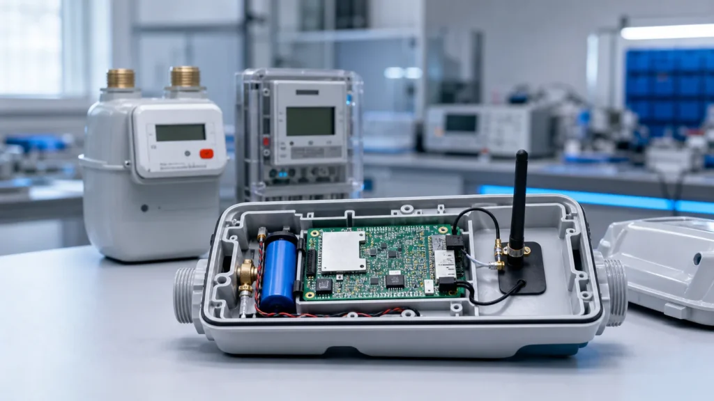
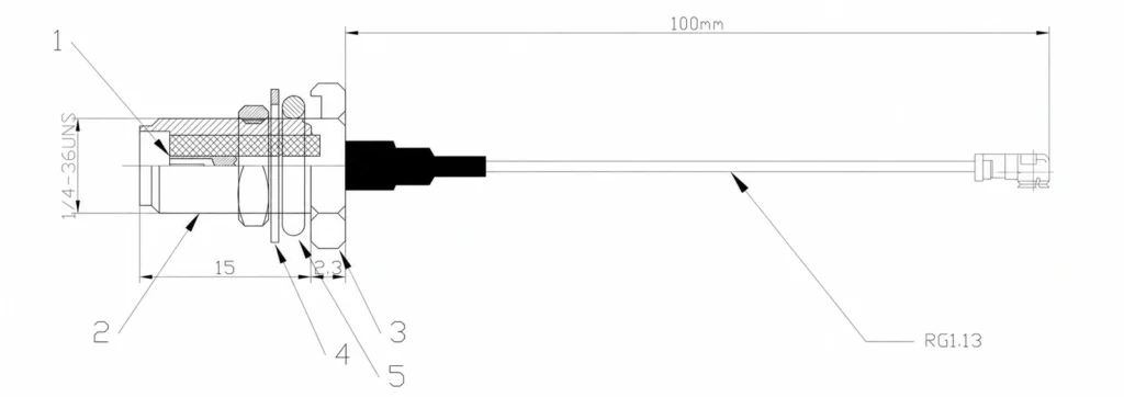
A miniature RF pigtail connects a board-mounted radio port to an external antenna connector. To choose one, match the exact connector interface, required frequency range, impedance, cable length and enclosure mounting arrangement. The C39 drawing provides a useful example: a 100 mm, 1.13 mm cable assembly with an SMA female bulkhead connector and an IPEX-labelled miniature connector, specified for 0–3 GHz. Its small size does not establish a 6 GHz rating.
What the C39 drawing actually specifies
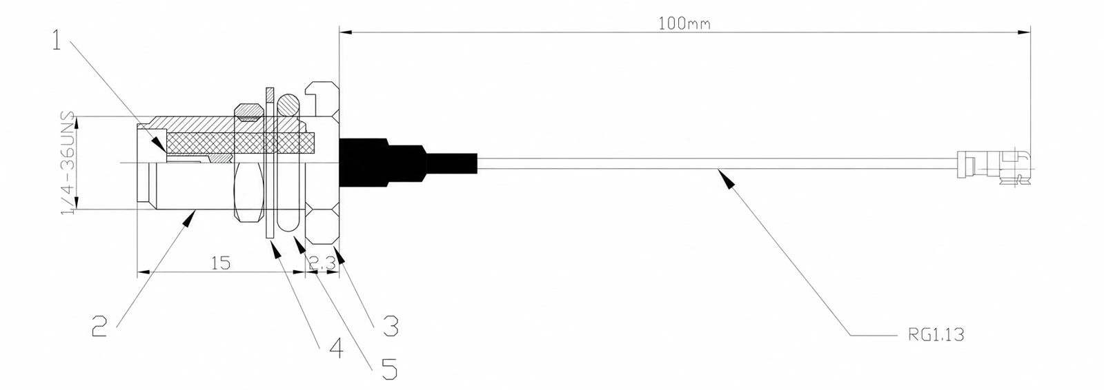
The C39 assembly drawing, revision A1 dated 15 October 2021, identifies the following configuration. These are drawing specifications, rather than a substitute for a frequency-swept test report on a delivered batch.
| Item | C39 drawing information |
|---|---|
| Cable | Black 1.13 mm coaxial cable, labelled RG1.13 |
| Length | 100 mm between the reference points shown in the drawing |
| Enclosure connector | SMA female bulkhead, 1/4-36 UNS thread |
| Threaded section | 15 mm as shown in the drawing |
| Board-side connector | IPEX-labelled miniature RF connector; exact mating series must be confirmed |
| Nominal impedance | 50 ohm |
| Frequency range | 0–3 GHz |
| VSWR | Less than 1.25, as listed in the drawing |
| Seal | Red silicone ring at the SMA mounting arrangement |
The drawing also identifies a PTFE insulator and gold-plated brass SMA body, nut and washer. It does not establish the complete cable jacket material, a RoHS declaration, an IP rating or insertion loss across frequency. Those items need separate confirmation when they matter to the design.
Match the frequency range to the radio
A 0–3 GHz cable assembly can be considered for a 2.4 GHz Wi-Fi or Bluetooth design, and for cellular or other radio bands that fall within that limit. Check the actual operating channels and required performance before approving the part. A connector with a higher individual frequency rating does not raise the rating of the finished assembly.
For 5 GHz Wi-Fi, a 3.5 GHz cellular radio or a design operating up to 6 GHz, select a different assembly with documented performance over the required range. Do not qualify C39 for those applications from its appearance or connector name.
For comparison, I-PEX publishes frequency and VSWR information for its own MHF I connector family. That information applies to the specified I-PEX products. It does not identify the manufacturer or mating series of an unmarked connector on another cable assembly.
Confirm both connector interfaces before ordering
“SMA to IPEX” is a starting description, rather than a complete mating specification. At the enclosure end, confirm SMA versus RP-SMA, the centre contact, thread arrangement and required bulkhead mounting hardware. At the radio end, identify the exact miniature receptacle and its mating plug from the module documentation.
C39 is drawn with an SMA female connector. Do not replace it with RP-SMA simply because a photograph looks similar. Likewise, do not assume every miniature connector described as “IPEX” fits the same board socket. Request a mating drawing or a sample and check seating, clearance and cable exit direction.
For standalone connector selection, compare the model-specific dimensions and ratings in the GL-SMAC SMA connector series. Those connector ratings remain separate from C39’s assembly specifications.
Route the cable without loading the board connector
A fine coaxial cable is useful inside a compact gateway, sensor or camera enclosure, but the route still needs mechanical clearance. Keep the cable away from sharp sheet-metal edges and pinch points. Allow enough slack for assembly without leaving a loop that can catch in the lid or fan.
Use the cable supplier’s minimum bend radius. The C39 drawing does not give one, so avoid inventing a numerical limit. Support the cable so that movement at the enclosure connector is not transferred to the miniature board connector. Follow the connector supplier’s mating and removal procedure rather than pulling on the cable.
The 100 mm dimension is tied to the reference points in the C39 drawing. If a project needs a different length, state the measurement convention and tolerance explicitly. Comparing overall length with a cable-only dimension can cause an assembly to arrive too short for the enclosure.
Treat sealing as an enclosure design requirement
C39 includes a red silicone ring, but the presence of a ring does not prove an IP67 or IP68 assembly. Sealing depends on the connector mounting face, panel hole, panel thickness, seal compression and the external mating arrangement.
For an outdoor installation, ask for the tested sealing configuration and environmental rating. Check whether the rating applies to the bulkhead installation, the mated external interface or the complete enclosure. Keep the board-side miniature connector inside the protected enclosure unless its own documentation says otherwise.
Separate electrical continuity from RF performance
Open- and short-circuit checks help detect wiring faults. They do not measure insertion loss or establish performance at the highest operating frequency. The C39 drawing says “100% tested” without naming the test method, so it should not be advertised as having a particular 100% RF test programme.
For design qualification, request results for the finished cable length and connector combination. Relevant checks include continuity, VSWR or return loss, and insertion loss across the required band. Agree on mechanical and environmental checks separately where the installation requires them.
A lower VSWR indicates less reflected signal at the measured interface, but it does not by itself state how much signal is lost through the cable. Keep both reflection and transmission measurements in the acceptance criteria.
What to include in a pigtail enquiry
Send the radio module’s receptacle reference, antenna connector type, operating bands, required length and tolerance, cable route and panel dimensions. Include any insertion-loss limit, sealing requirement and compliance documents needed for the project.
Use the C39 drawing as a reference only when its 1.13 mm cable, 100 mm dimension and 0–3 GHz range suit the design. For a different frequency or mechanical requirement, request a separately specified assembly. The custom RF assembly example shows why board-side integration and cable construction should be reviewed together; the RF coaxial adapter range covers a different product form and should not be treated as an interchangeable pigtail.
RF cable assemblies
Specify your SMA-to-IPEX pigtail
Send the board connector reference, operating band, cable length and panel dimensions. We will review the interface and assembly requirements.
Ask our AI antenna assistant. Enter a keyword or question for a free answer based on this article, Global RF Tech content, and general antenna/RF knowledge.
Do not submit confidential or personal information. Privacy Policy